 |
|
|
|
|
|
|
|
|
|
|
|
|
|
|
|
|
|
|
|
|
|
|
|
|
|
|
|
|
|
|
|
|
|
|
|
|
|
|
|
|
|
|
|
|
|
|
|
|
|
|
|
|
|
|
|
|
 |
|
|
|
|
|
|
|
|
|
|
|
|
|
|
|
|
|
|
|
|
|
|
|
|
|
|
|
|
|
|
|
|
|
|
|
|
|
|
|
|
|
|
|
|
|
|
|
|
|
|
|
|
|
|
|
|
|
|
|
|
|
|
|
|
|
|
|
|
|
|
|
|
|
|
|
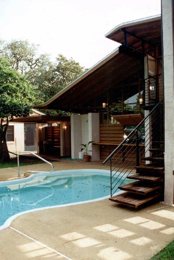
Smolka Garage / Poolhouse
Tampa, FL
1996 - 1998
"The Grand Garage" St. Petersburg Times Coverage
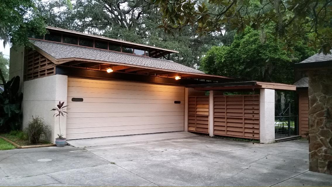
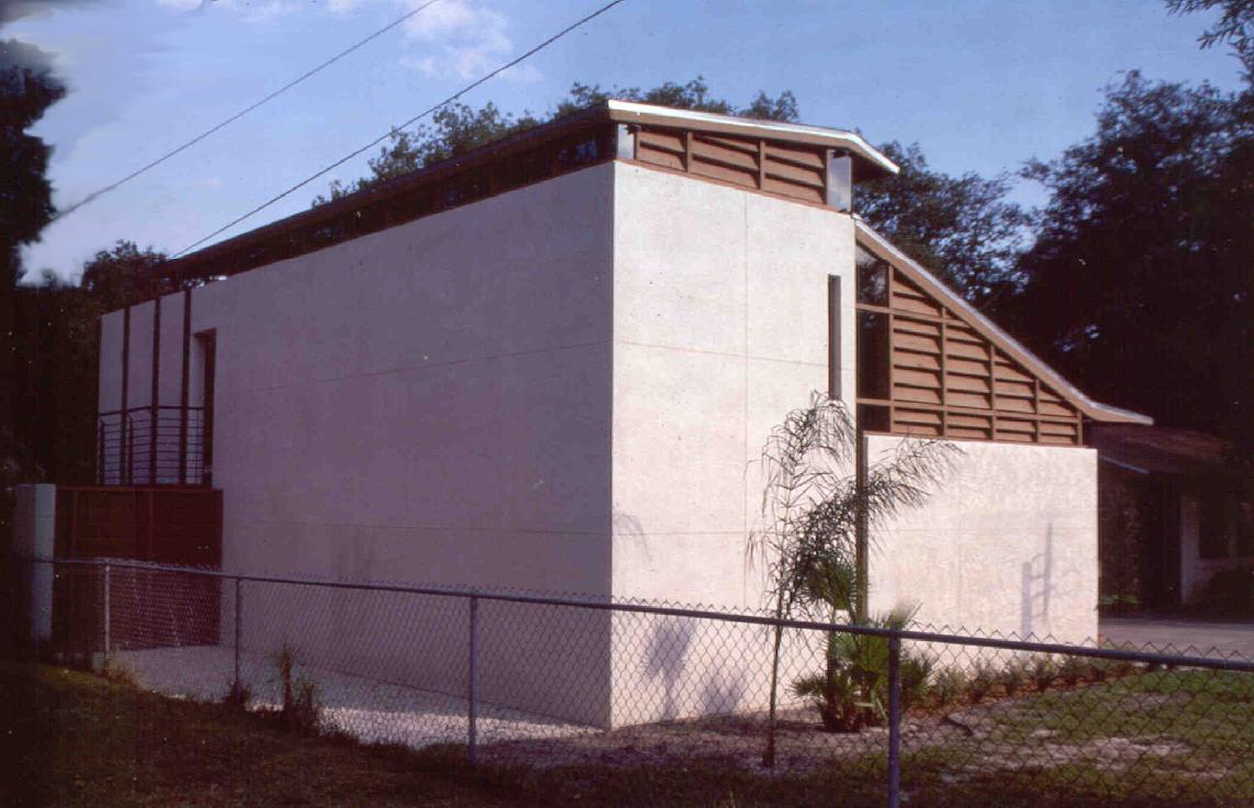
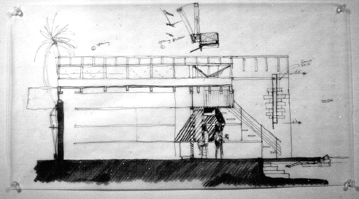
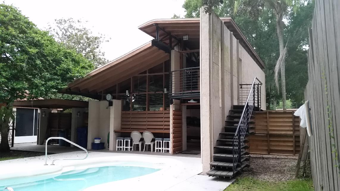
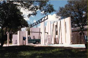
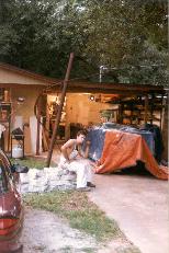
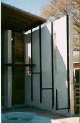
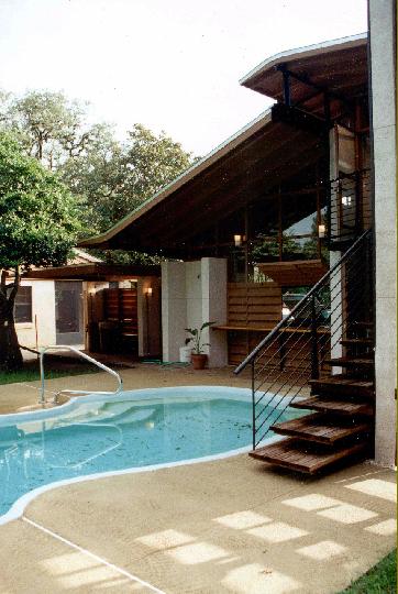
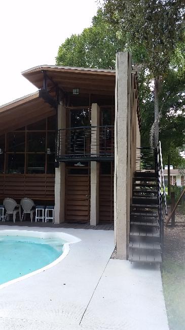
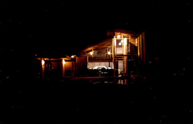
At the outset of the project, an overall direction for the project had to be established that would enable a collaborative connection between new and existing structures. To the street edge, the new structure would present a subtle face and attempt to make a soft transition from the height and detail of its own composition to that of the existing house. The 2 level roof system will float as a pair of wing-like planes above a concrete shell and express a height that soars up only for an instant, then sinks in elevation to join its existing, parent structure. To the passer-by, the new structure will rest quietly as a participant, relating to its context in terms of materials and scale, while maintaining its own identity in terms of detailing, massing, and composition.
|
|
|
|
|
|
|
|
 |
|
|
|
|
|
 |
|
|
|
|
|
|
 |
|
|
|
|
|
|
|
|
 |
|
|
 |
|
|
|
|
|
|
 |
|
|
|
|
|
 |
|
|
|
|
|
|
 |
|
|
|
|
|
|
|
|
|
|
|
QUESTIONS:
what is garage
what is a room by the pool
container for cars
living space @ pool
The project comes to be about the edge between the two. The importance of the project belongs to that transition between the space for cars and the space of the pool.
|
|
|
|
|
|
 |
|
|
|
|
|
 |
|
|
|
|
|
|
 |
|
|
|
|
|
|
|
|
 |
|
|
|
|
|
|
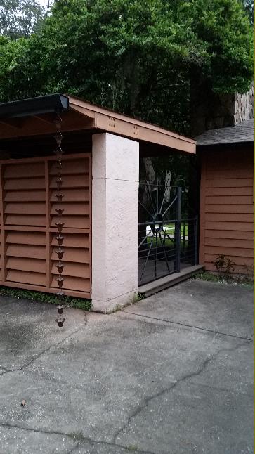
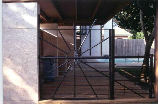
The ground level plan shows the development of the east edge of the project as an active, mediating edge between the garage space and the outdoor living space of the pool. The edge becomes a thickened, occupiable one that is transparent yet provides multiple, functional aspects for the spaces it defines. The series of vertical CMU fins at the east edge complete a diagram of a shell system that defines generally the spatial organization of the structure. The series of fins define a penetrable edge that suggests to the user many options for use such as storage, or niches for placing tables and chairs.
|
|
|
|
|
|
|
|
|
|
|
 |
|
|
|
|
|
|
 |
|
|
|
|
|
|
|
|
|
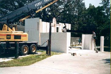
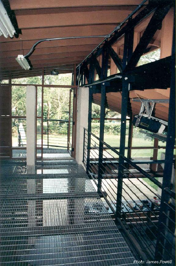
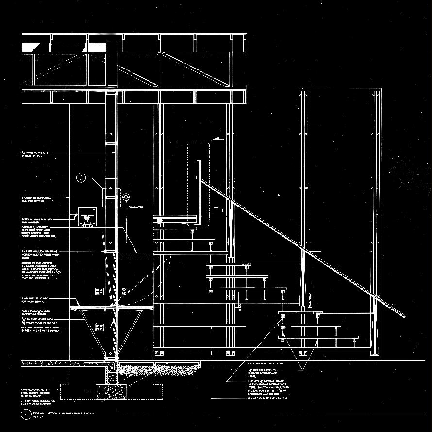
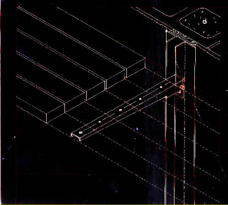
Above: This construction photo shows the steel structural elements that compliment the CMU / stucco shell and complete the main wind force resisting structure. The double angles running horizontally from the top of the I-shaped wall through the two, tall fin walls transfer the lateral forces from the 40' long, 15' high wall at the north into the I-shaped section of wall at the southeast. This wall with its I-shaped plan-section provides an extremely rigid structural form in CMU / cast in place concrete which also provides a poche element for a shop sink at the inside and an outdoor shower and faucet at the outside. Also provided for in the CMU / shell wall system is electrical systems. In this photo, the north most double angle section is not installed yet because of an additional cell in the CMU wall needing filled due to the insertion of the stair opening after the beginning of construction.
|
|
|
|
|
|
|
|
|
|
|
 |
|
|
|
|
|
|
 |
|
 |
|
|
|
|
|
|
|
|
|
|
|
|
|
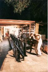
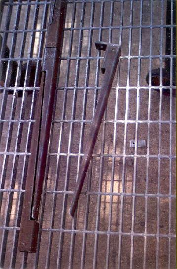
Steel truss & beam just after completed fabrication at the studio. The beam weighs in right about 1,100lbs & the truss comes to just over 1,200lbs.
|
|
|
|
|
|
|
|
|
|
|
|
|
 |
|
|
|
|
|
 |
|
|
|
|
|
 |
|
|
|
|
|
|
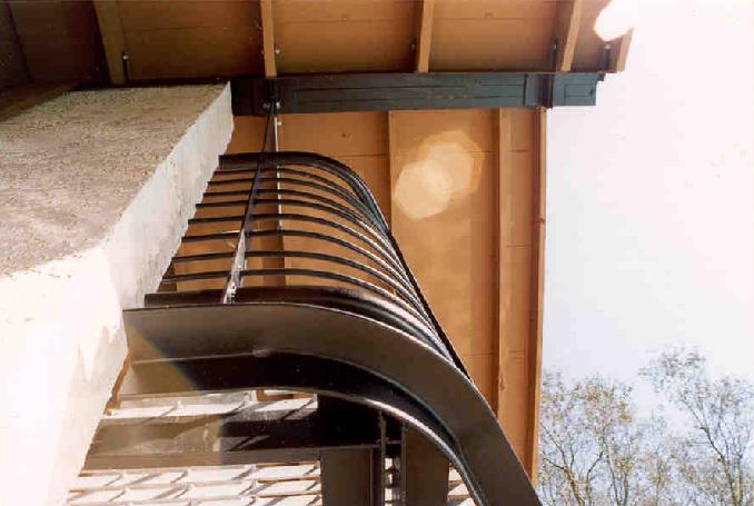
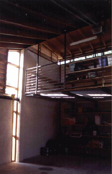
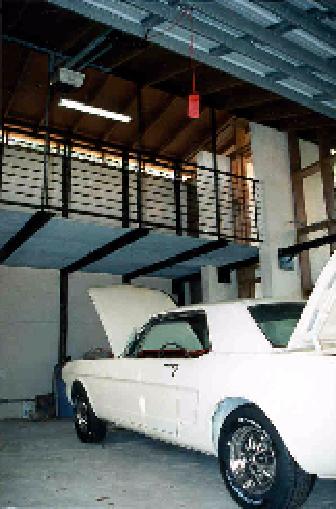
A major part of the program for the project is the storage space requirement. This element of the program is incorporated as a linear element at the north of the composition and becomes a transparent plane that floats above the noses of the cars via steel flat bar hangers and double angle pilasters on the north wall. The flooring material had to be something that is durable, maintenance free, and would let light penetrate through it to the space below. A galvanized steel, 1" bar grating comes in standard 3' x 20' lengths and efficiently and economically provides all of these requirements. Installation of the grating is very simple and is accomplished by spot welding the grating to the steel double angle supports which are suspended from the truss above. The vertical circulation is then structurally integrated with the north wall and designed as a removable element that may be used as storage shelving.
|
|
|
|
|
|
|
|
|
|
|
 |
|
|
|
|
|
|
 |
|
|
|
|
|
|
|
|
|
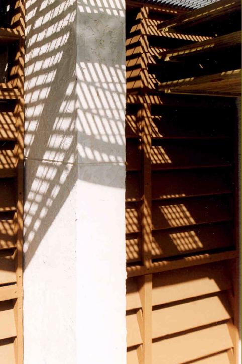
Above: the zinc content in the galvanizing is reflective and depending on the time of year and day, the grating actually becomes a light source for the first level.
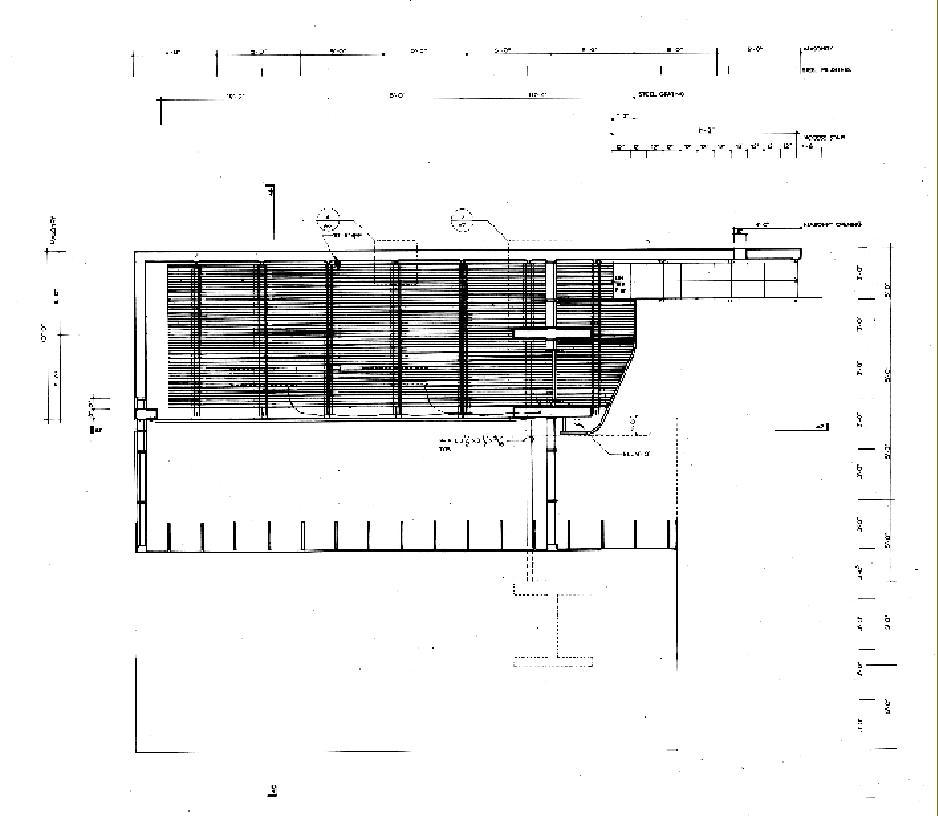
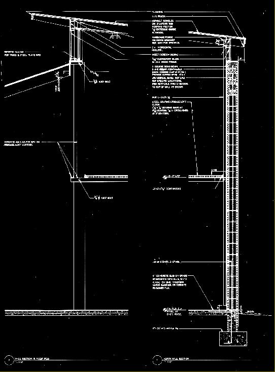
Right: second level plan at storage loft
|
|
|
|
|
|
|
|
|
|
|
|
 |
|
|
|
|
 |
|
|
|
|
|
|
|
|
 |
|
|
|
|
|
|
|
|
|
|
 |
|
|
|
|
|
|
|
|
|
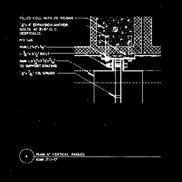
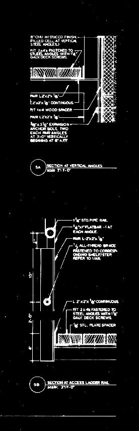
The removable stair is developed as a planar system that is suspended via 1/2", galvanized, threaded rods, and 3 main steel brackets that are anchored between the protruding legs of two steel angles bolted to the north CMU wall. The pairs of angles are a repetitive system that repeats at each filled cell (4'-0" o.c.) on the inside for the length of the wall - also serving here to allow the roof plane to float over top of the CMU shell system - and at the eastern most 12' of the outside of the north wall. This standard spacing of the double angle system allows flexibility of placement of brackets, shelving, and other systems designed for attachment to the double angles.
|
|
|
|
|
|
|
|
|
|
|
 |
|
 |
|
|
|
|
|
|
|
|
|
|
Above left: the double angle pilaster and steel bracket system.
Above Right: suspended stair-shelving
|
|
|
|
|
|
|
|
|
|
|
 |
|
|
|
|
|
|
 |
|
|
|
|
|
|
|
|
|
|
|
|
 |
|
|
|
|
|
|
 |
|
|
|
|
 |
|
|
|
|
|
|
 |
|
|
|
|
|
|
|
|
|
|
|
|
|
|
|
|
|
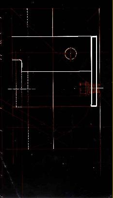
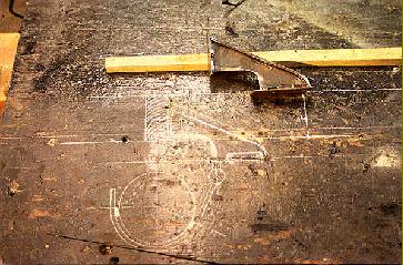
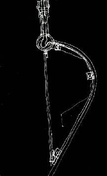
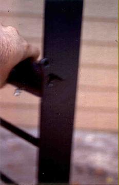
Above: initial sketch of the stair bracket system
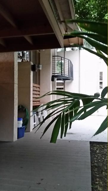
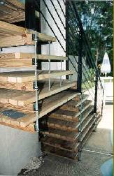
Right: photo (2018 rebuild in composite lumber) showing the stair system removed from its original position and re-assembled at the north side of the wall. This location utilizes the opening placed into the north wall. The opening becomes an aperture that one passes through, entering an active space from the subtle, outside space at the north of the wall.
Below: lower of 3 stair support brackets.
|
|
|
|
|
|
|
|
|
|
|
|
 |
|
|
|
|
|
|
|
|
|
|
|
|
The Double Angle Pilaster
This set of images shows more of the development of the stair system and its versatility due to the development and incorporation of the double angle pilaster. Also developed is a system of shelving that may be attached to the double angles at any point. The concept is that a bracket is designed that will slip between the double angles and may be clamped in place with the use of a 3/8" dia. bolt. Additionally, there is an angle adjustment bolt at a steel flange beneath the arm for leveling purposes. This simple bracket may be attached at any point on the double angle pilasters and is fabricated by torch cutting a simple interlocking pattern from a 1 1/2" x 1 1/2" steel square tube.
|
|
|
|
|
|
|
|
 |
|
|
|
 |
|
|
|
|
|
|
|
 |
|
|
|
|
|
|
|
|
 |
|
|
|
|
|
|
|
|
Left: the torch cut, interlocking arms. The piece to the right has the leveling flange welded in place.
Right; ink on mylar detail of the arm to pilaster joint with the leveling bolt.
|
|
|
|
|
|
|
|
|
|
|
|
|
|
 |
|
|
|
|
|
|
|
|
|
|
|
|
|
|
|
 |
|
|
|
 |
|
|
|
|
|
|
|
|
|
|
|
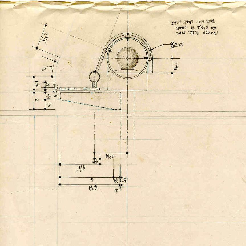
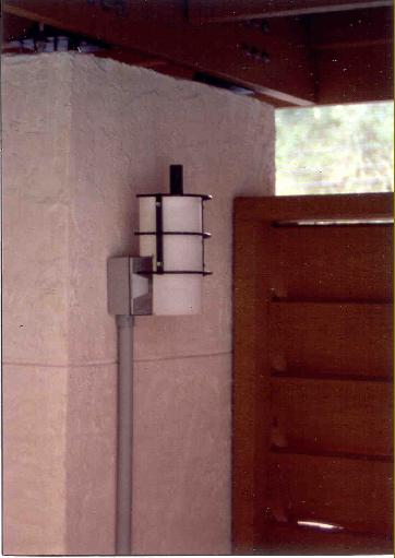
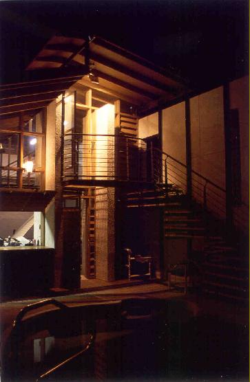
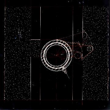
At the detail level there is a need to conceptually tie together the building elements. The light fixtures are developed as a two part composition in which a steel structure holds a light manipulation mechanism. Not unlike the overall construction of the project where a masonry shell is a primary structural system and is interdependent with a steel, wood, and glass system, - each having a specific, functional task - the light fixtures separate functionality through its construction material systems. The light sconce is developed to economically shield and disperse the light from the essential, outdoor fixture box. It consists of a simple steel cage that bolts to the CMU wall with masonry screws. A frosted acrylic shield is then held in place by use of #10NC24, stainless steel allen head cap screws. The making of the acrylic shield is similar to the process of making the steel shelving arms in that an interlocking form is cut from a continuous tube. This allows a portion of the tube to slip over the incandescent lamp to shield and diffuse the light.
|
|
|
|
|
|
|
|
|
|
|
|
|
 |
|
|
|
|
|
|
|
 |
|
|
|
|
|
|
|
|
|
|
 |
|
|
|
|
|
|
|
|
|
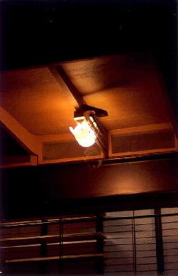
This fixture uses the same concept of a steel cage holding a device that will alter and transform the way that the light is emitted. The placement of the fixture - at the under side of the roof - and its function of illuminating both the upper and lower doorways determines a need for an asymmetrical distribution of light. An asymmetrical reflector is developed using .010" aluminum sheet (for its reflective qualities) held by 2 cypress ribs that give the reflector its shape. The steel grating of the loft floor is key in this instance because we are able to use one fixture to illuminate two doorways that are one atop the other.
|
|
|
|
|
|
|
|
|
 |
|
|
|
|
|
|
|
|
|
|
|
 |
|
|
 |
|
|
|
|
|
|
|
|
|
|
|
|
 |
|
|
|
|
|
|
|
|
|
|
Top: Photo showing the asymmetrical throw of light due to the shape of the aluminum reflector.
Above: The parts of assembly. The fixture uses a 300W halogen lamp.
Right: initial sketch of the halogen asymmetrical reflector lamp.
Far Right: sketches developing the product and its parts.
|
|
|
|
|
|
|
|
|
|
|
 |
|
|
|
|
|
|
 |
|
|
|
|
|
|
 |
|
 |
|
 |
|
|
|
|
|
 |
|
|
|
|
|