|
Guest House (at 1012 Canal Street, Ruskin, FL)
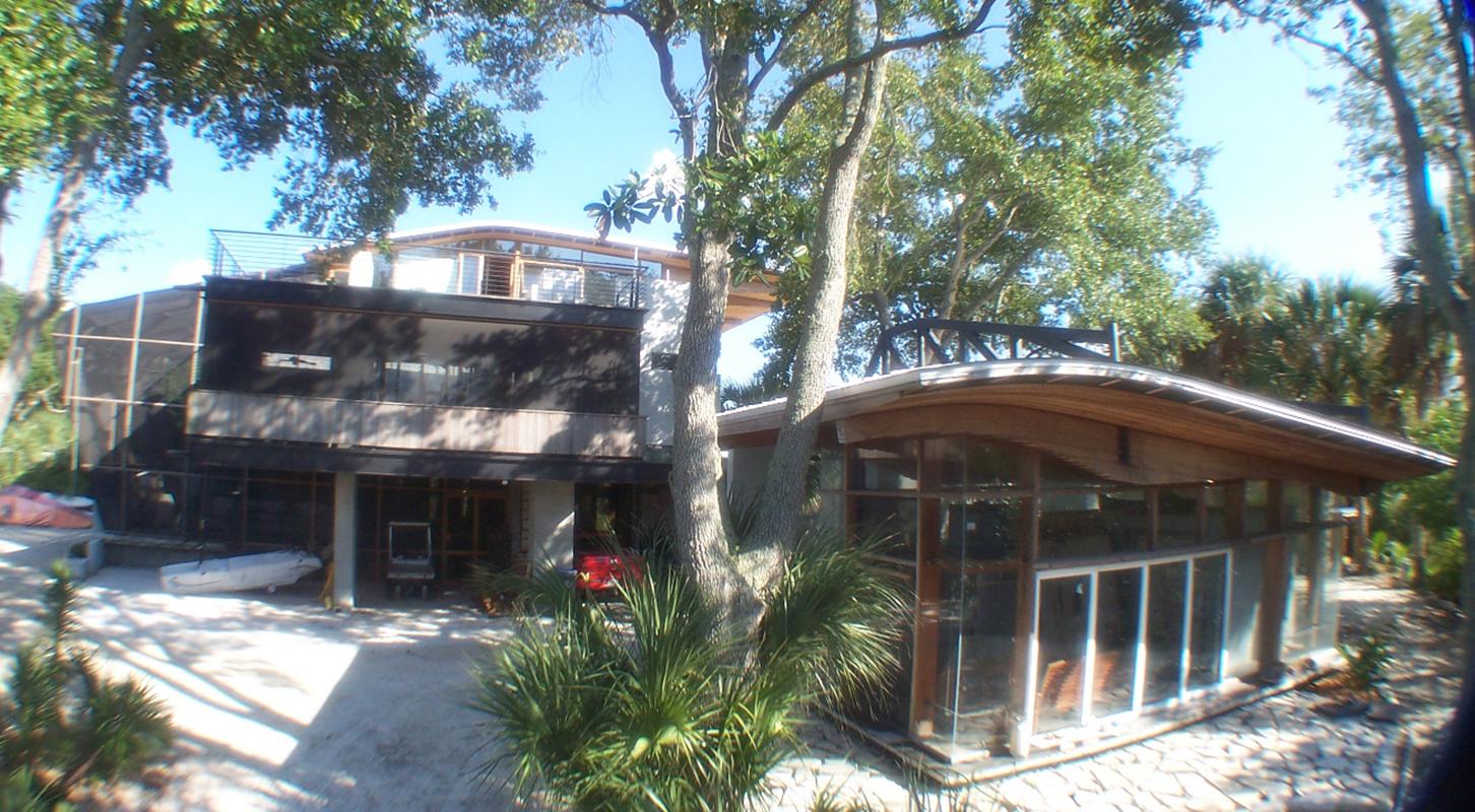
Grounded . . . Floating, a structure that anchors itself at one edge creating a screening/private edge with thick, carved, masonry elements while allowing the other edge to float out over an EPC wetland area and reach toward the canal and the bay. The floating edge disintegrates into glass and cypress framing members with suspended corners & light, delicate steel members defining boundaries and corners. |
|
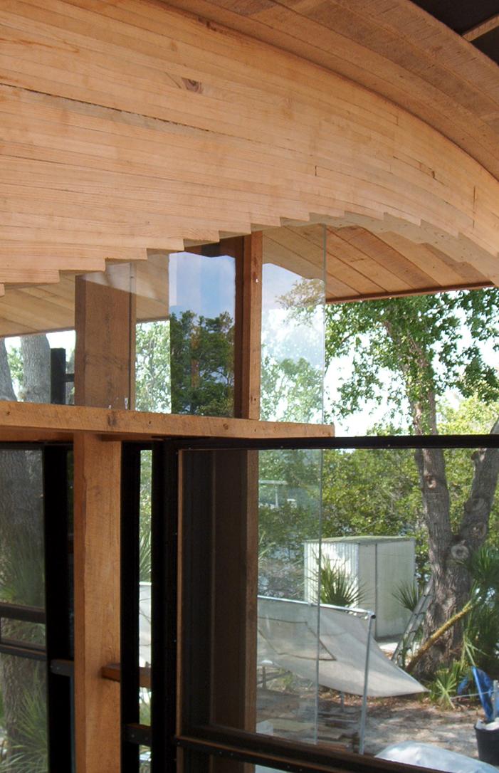
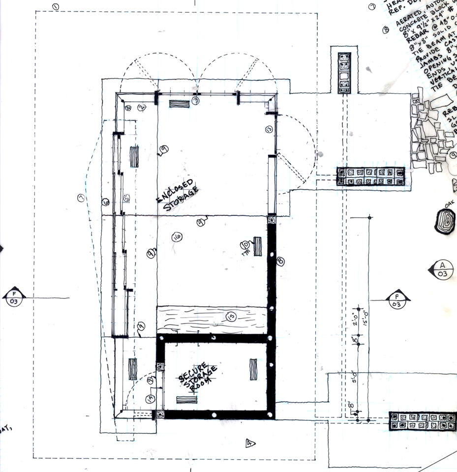
The Plan is laid out like a small hotel room providing an enclosed space at the southeast corner that may serve utilitarian functions while the open space to the north of this is screened at the east by the structural piers beyond the glass line and by the extension of the solid, masonry wall enclosing part of the eastern edge of the space. This space becomes the served space so to speak, the living/sleeping space. The solid masonry edge extends up only 7 1/2 feet to exist as a ruinous wall over which the roof system floats. Closure between the masonry shell and the floating roof is nothing but glass and a few thin cypress mullions to contain the glass. |
|
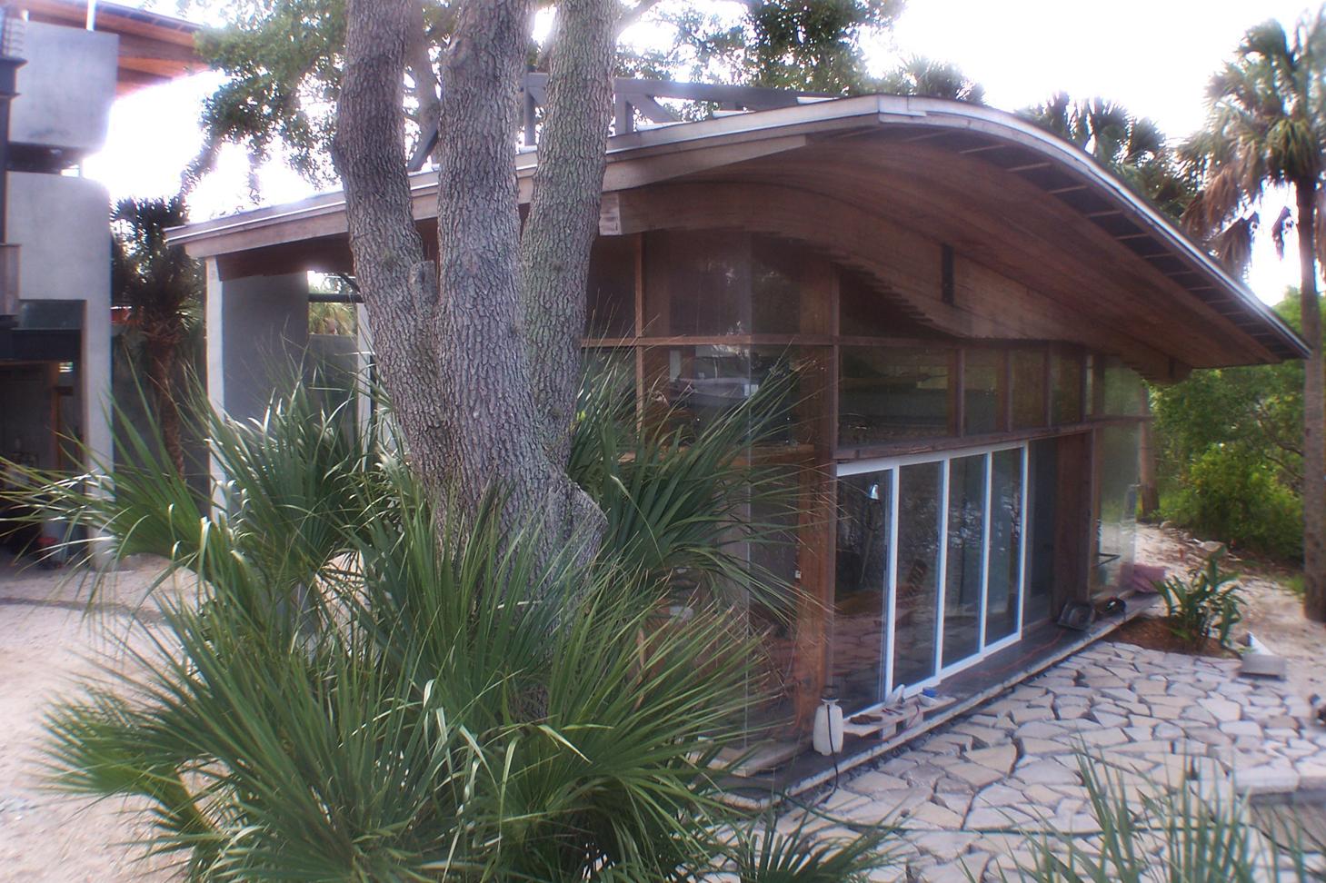
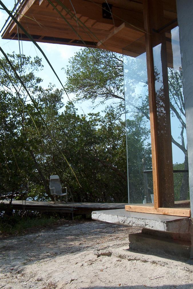
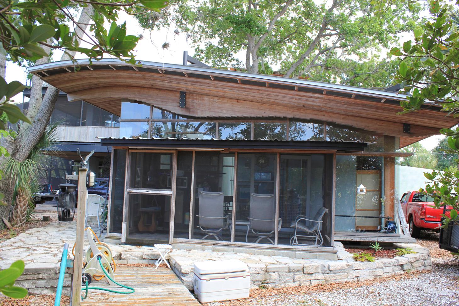
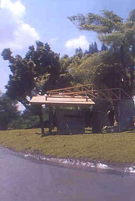
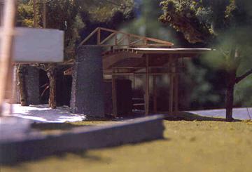
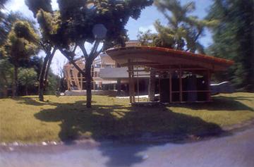
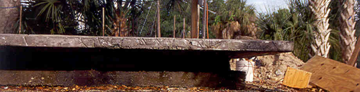
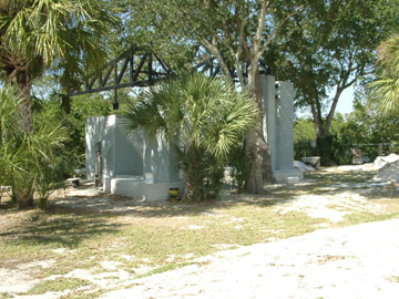
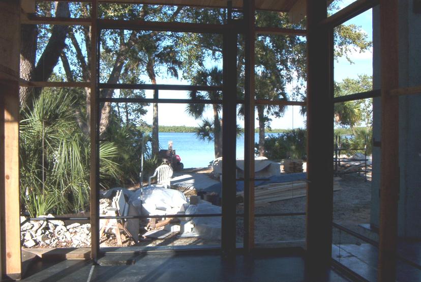
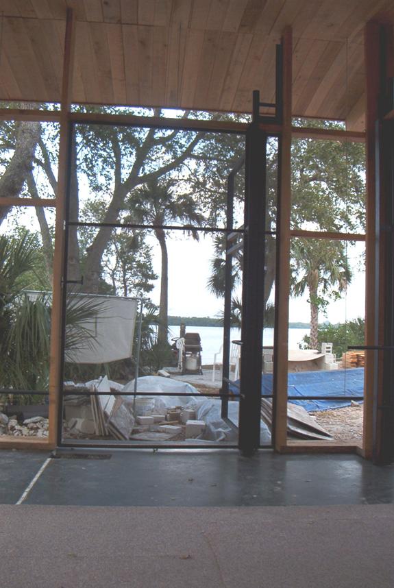
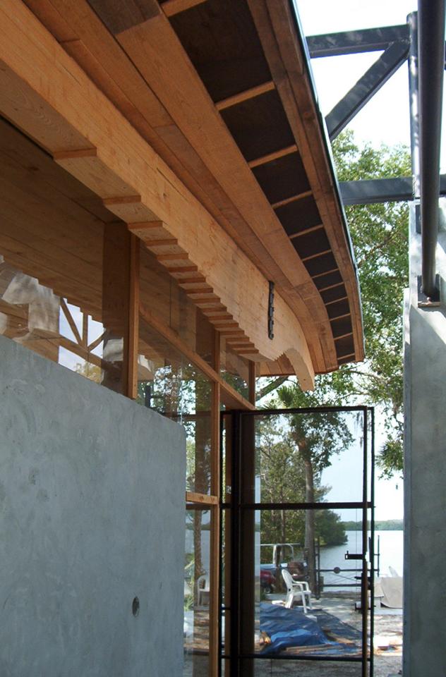
Right: the water of the mouth of the river can be seen between the piers and the edge of the cottage. The sense of this structure is that it is grounded at the right, and floats out toward the canal and the bay. The materials and composition move from a massive, solid system at the right (east), to a light, more delicate system that disintegrates, tapers and floats out toward the dense mangroves and the water at the left (west). |
|
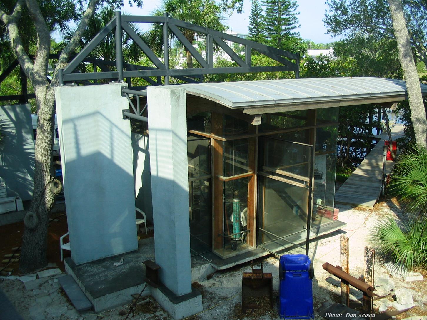
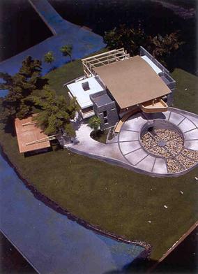
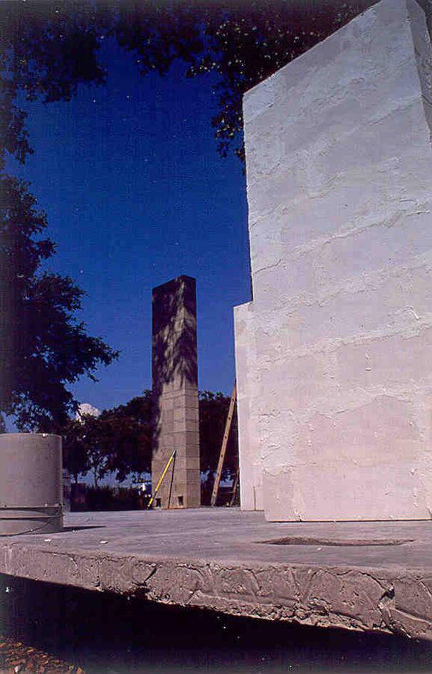
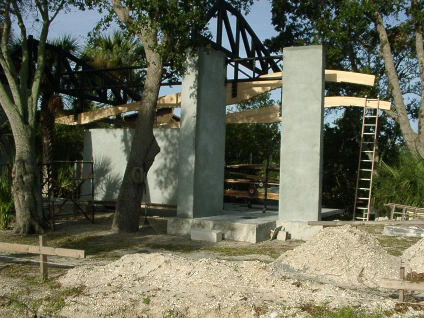
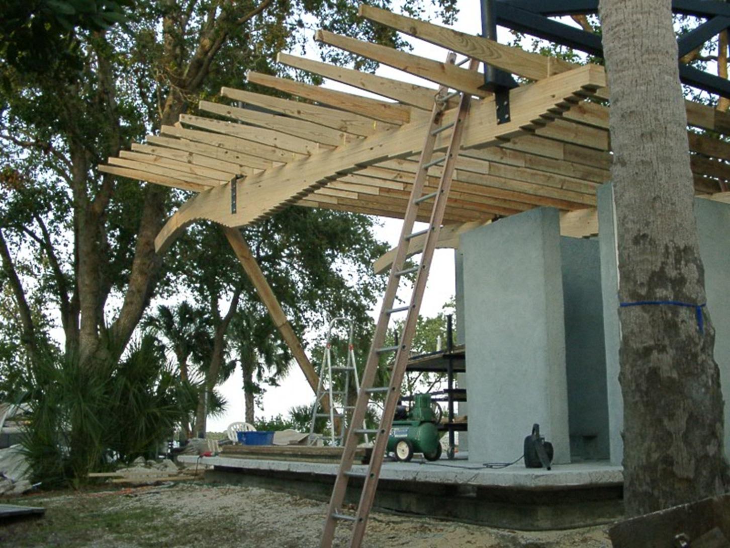
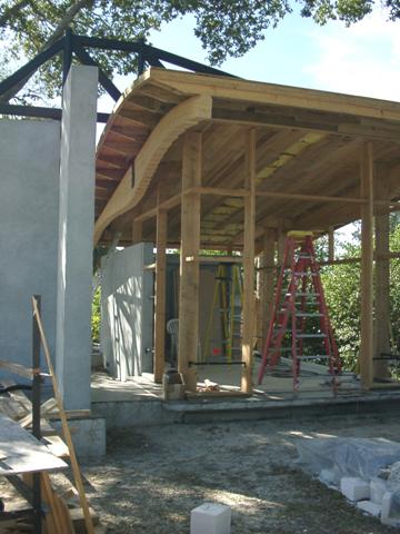
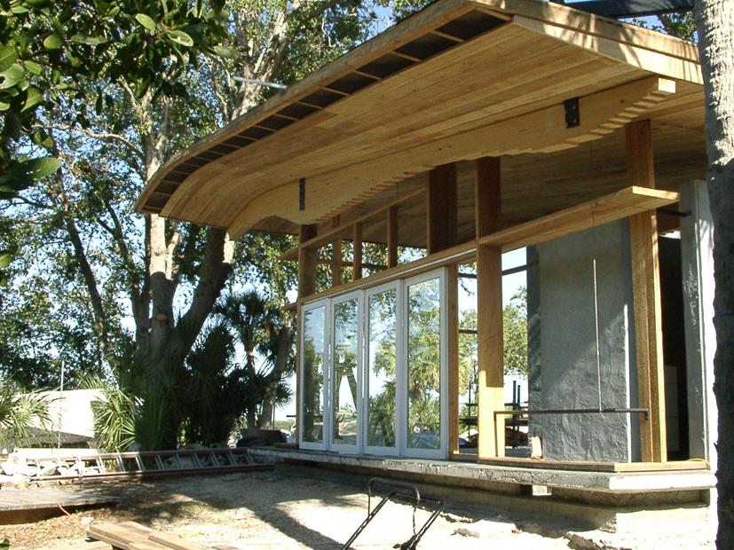
This series of photos shows the way the guest structure becomes a hovering plane that is suspended by two massive piers much like a davit would hold a boat over water. The EPC wetland zone, within 25 feet of the west edge of the property becomes this sacred zone within which we could place no new structure, hence the piers outside of this zone to reach into it, creating space. |
|
To further enhance the floating quality of the guest house floor, the concrete slab steps up 4 inches above the existing concrete and cantilevers with a taper 12 inches beyond the boundary of the existing slab..
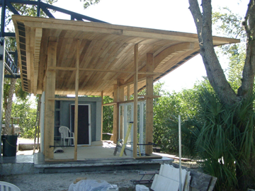
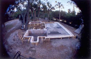
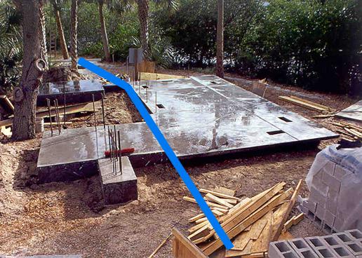
Above: the foundation forms are seen and one can see the massiveness of the bases (at the left) for the piers that will support the massive steel trusses that will suspend the roof structure above the space. |
|
The blue line at right represents the edge of the EPC wetland zone.—the slab within the wetland zone is on top of an existing slab which had no reinforcing and no footings. |
|
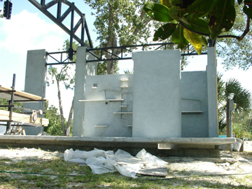
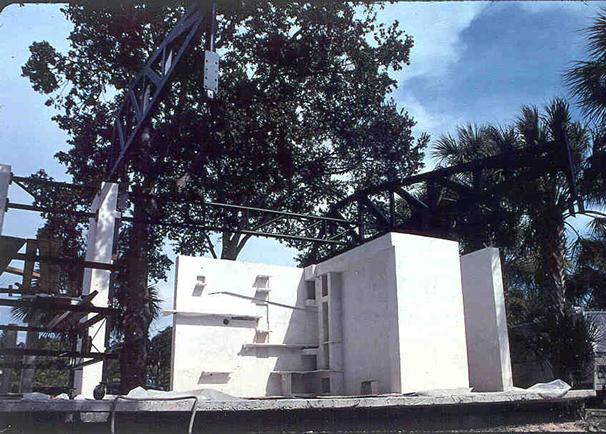
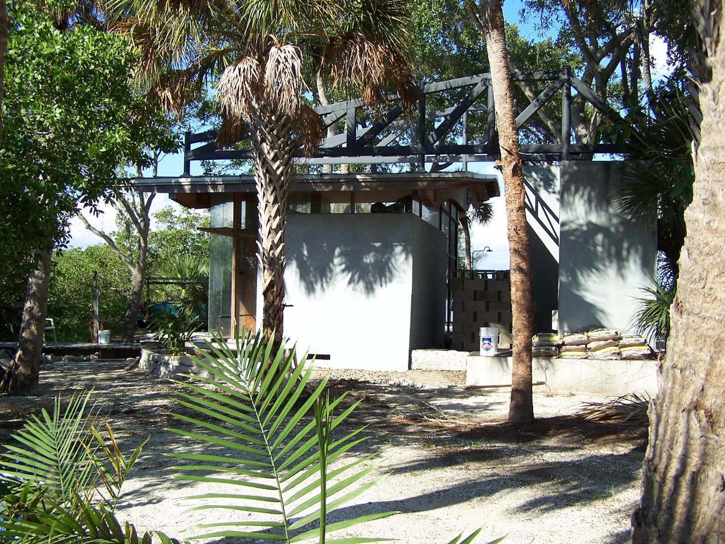
Above: The shell is seen here after the blue pigmented grey stucco is finished . . . The colors change in hue with more or less cloudiness . . . The bright blue of the sky intensifies the blue-ness of the shell. |
|
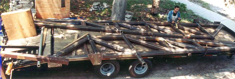
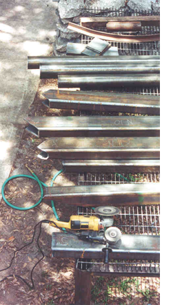
The summer of 2001 is when most of the elements for/of the guest were made, Jason Jensen of Clearwater came out for most of the summer for some steel grinding, concrete carving, tractor operating, and more fun . . . These trusses were made by Calvino & Jensen, in maybe 3 weeks ? . . . The long truss is 26’ long and weighs about 2100# while the shorter one is 22’ long and almost 1900#! |
|
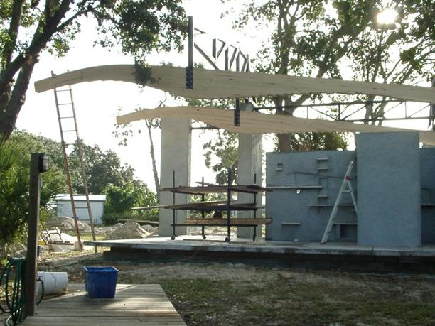
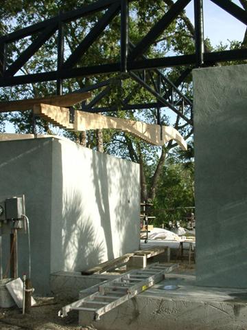
Left: the south truss is seen here cantilevering among the trees, the steel forks hang there . . . Waiting for the glu-lam beams . . . |
|
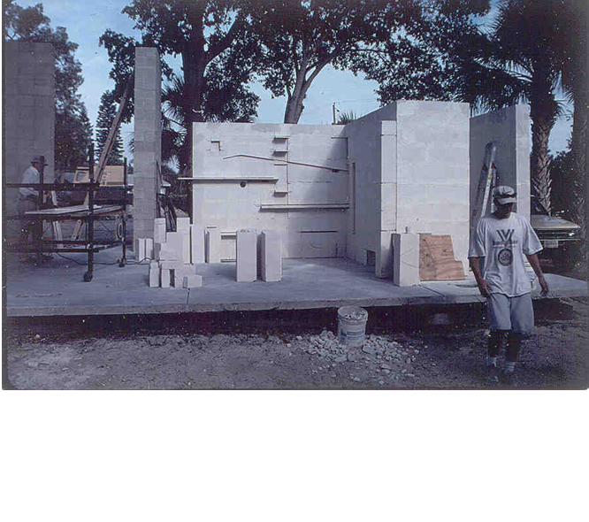
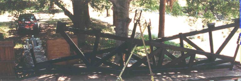
Right: The carved shell can be seen here, a queen size bed will eventually fold up into the relief seen at the south wall (at the right of the open space). The trusses can just be made out within the shadows of the trees here . . . The day of the truss setting was an extremely satisfying day for Calvino & Jensen . . . Even the crane operator, Milton, was impressed that everything bolted up with no hang ups . . . The trusses were hoisted up over the trees and dropped down onto their seats . . . The most challenging part was hanging the transverse truss . . . A wind brace truss . . . It runs from the pier at the north (left) to the truss at the south (right) - the operation was hang the truss there to start the bolt holes in the masonry pier, pick up the truss, then finish drilling the holes, re-place the truss, bolt the north end, then move to the south end and weld it to the south truss—we had to pull the south truss about 1 inch north to close a small gap between it and the transverse truss . . . Our biggest hang up . . . |
|
Jason left at the end of the summer, before we got to the glu-lams . . . we were sad to see him go, but he headed to New York City . . . the metropolis . . . To see what damage he could do there . . . Hope to see you soon! |
|
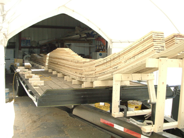
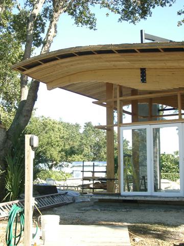
Here we finally made the glu-lams . . . After spending at least a week’s time calling what seemed like every glu-lam distributor in the southeast, and getting nowhere . . . sending drawings to what I gather is the manufacturing plant (only one??) in the southeast US . . . and getting nowhere (I just got the drawing/spec package that I sent them sent back to me in the mail . . . No letter, nothing) . . . I decided to build them myself . . . With the owner’s invaluable help I started with rough sawn cypress, and within a little over a week, we had planed them, cut each one according to the drawing I’d made showing each lamination, its location and length, glued & screwed them, we had 2 beams . . . sculpted as the moment forces had dictated, 33 feet long, and weighing about 300# each! . . . We were able to hang them up in one afternoon. |
|
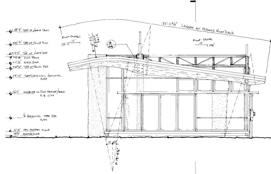
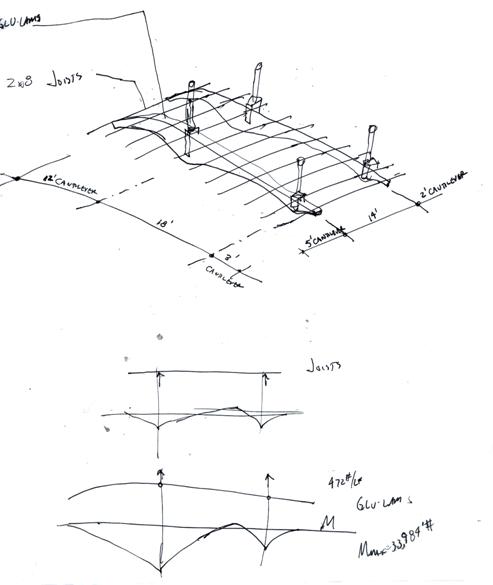
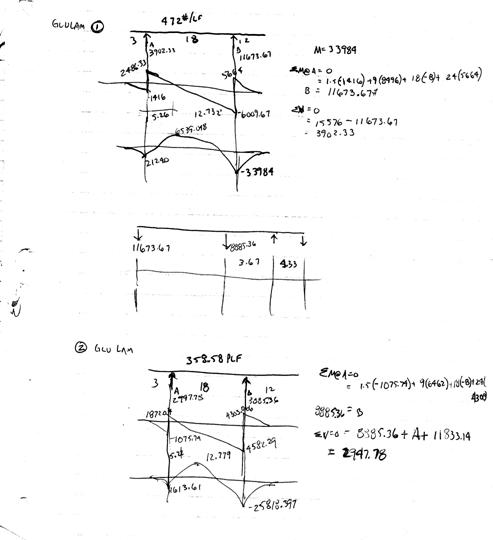
The size and shape of the Glu-lam beams is defined by the loading conditions imposed on them by their span and the roof configuration. The roof cantilevers 5 feet beyond the western beam and 2’ beyond the eastern beam increasing the reaction at the west beam. This condition results in a loading of 472# per foot along the glu-lam. In addition, the glu-lam has a 3 foot cantilever at the south end but a 12 foot cantilever at its north end with a span of 18’, this produces a maximum moment of 33,984 foot pounds. For strength alone, the beam would need a section modulus of 218.7in3, which translated to a 15 inch deep beam with a 6 inch width . . . However, it must be designed to limit deflection to at least l/360 because of the glazing that frames into the ceiling . . . With the relatively low modulus of elasticity of Southern Cypress at 1,100,000psi, and using the deflection formula for a cantilever beam to solve for I (moment if intertia of the section) we develop a section that is 6in wide by 24 in deep at the greatest stress point . . . at the northern support point at the truss. Other points are calculated in the same manner to solve for depth of beam, then we sculpt the shape to smooth the curves . . . And we arrive at the final beams. |
|
Right Above: is a diagram of the support conditions of the guest house roof . . . The double cantilever creates a larger stress point at the northern support of the glu-lams . . . The deepest point of the beam.
Right: Shear & moment diagrams & calculations of the beams for sizing. |
|
©2025 CALVINO architecture studio, inc all contents of this publication whether in digital or analog format are the express property of CALVINOarchitecture studio, inc. and shall not be reproduced by any means without written consent from Mike Calvino |
|
The Ruskin House: Guest House |