 |
|
|
|
|
|
|
|
|
|
|
|
|
|
|
|
|
|
|
|
|
|
|
|
|
|
|
|
|
|
|
|
|
|
|
|
|
|
|
|
|
|
|
|
|
|
|
|
|
|
|
|
|
|
|
|
|
|
|
|
|
|
|
|
|
|
|
|
|
|
|
|
|
|
|
|
|
|
|
|
 |
|
|
|
|
|
|
|
|
|
|
|
|
|
|
|
|
 |
|
|
|
|
|
|
Steel, Maple, Stainless Steel
|
|
|
|
|
|
|
|
|
|
|
|
|
|
|
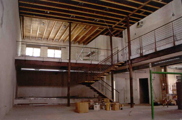
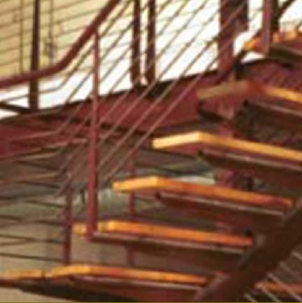
Self Supporting Stair with mezzanine level railing and cantilevered balcony. 1999
The project ended up as incomplete as the owner ran out of funds to finish the structure.
|
|
|
|
|
|
|
|
|
|
 |
|
|
|
|
|
|
|
|
|
|
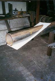
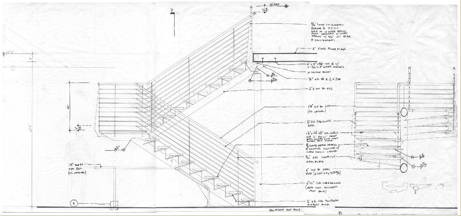
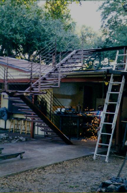
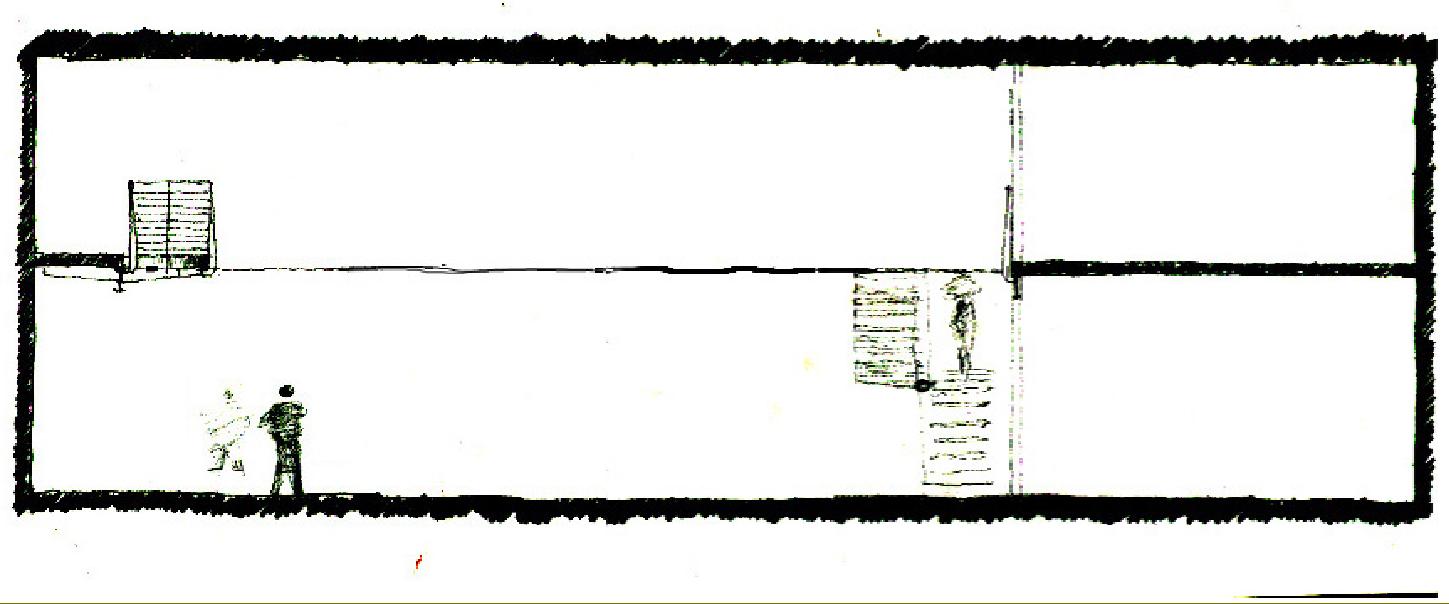
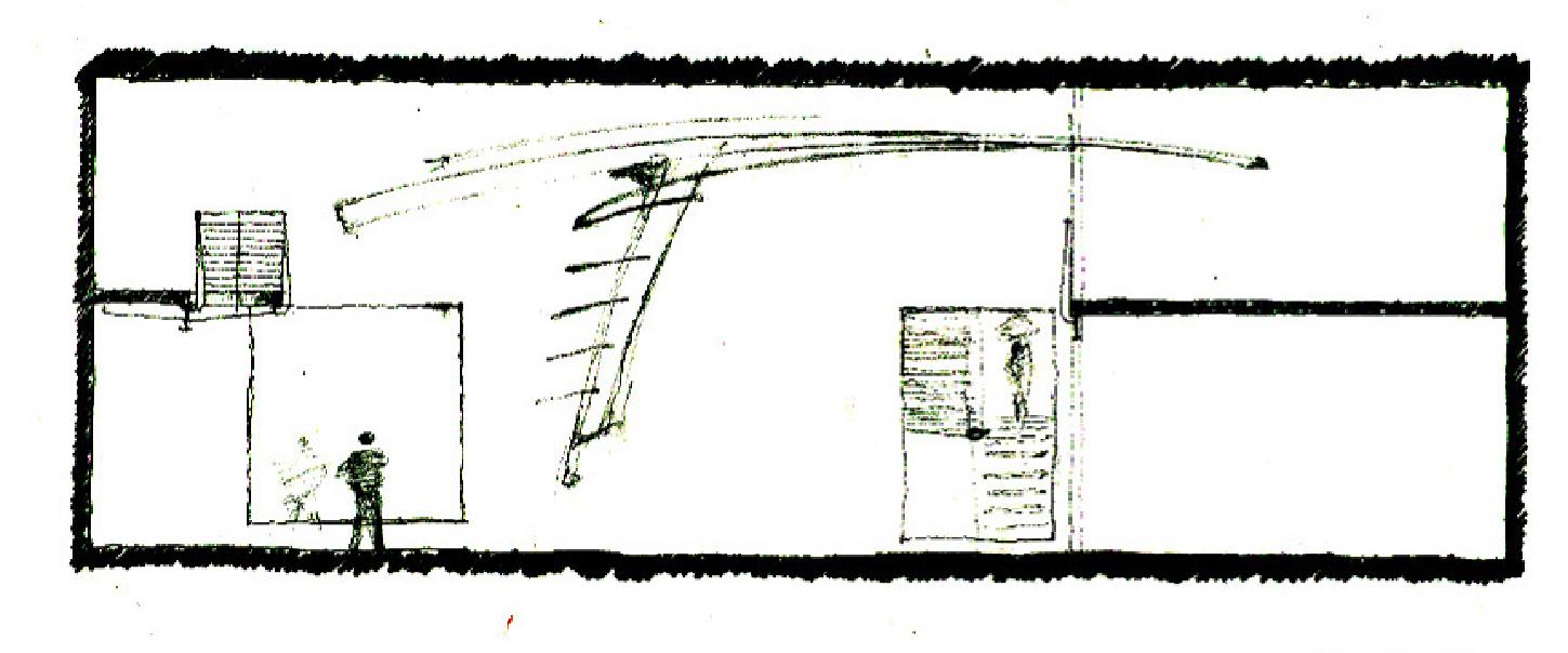
The concept for the stair is to provide an element that allows one to occupy the large volume of living space measuring roughly 20'high x 35' wide x 75' long. The intent is to bring one out into the space as if to float into its middle. The stair must be supported only at the edges of the space an must not touch down within the limits of the two story volume of space. The stair is developed to have very minimal structure and appear to be reaching into the space. This lightness is emphasized by expressing the advantageous properties of steel and the cylinder. The steel pipe is the stiffest steel section by weight and can resist torsion very well, in addition to bending, tension, and compression. So, to express this strength, the stair's structure consists of a 6" sch. 80 steel pipe that acts as a spine and resists torsion from the cantilevered treads, bending as a lateral force imposed at the landing, compression in the lower spinal stringer, and tension in the upper spinal stringer. By allowing this single pipe and by utulizing the thicker wall version (the schedule 80) to provide all of the structural resistance, the entire composition is lightened up and the outside diameter is minimized and gives the sense of floating and an unobtrusive element that extends into a large open living space.
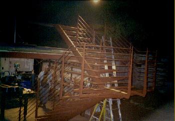
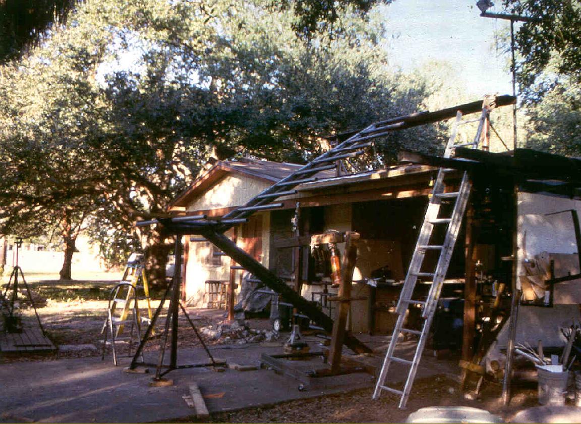
Far Right: the stir structure and railings in place.
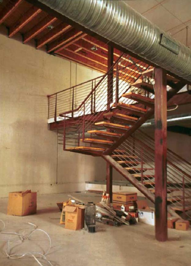
Right: the stair structure in its fabrication location at the Calvino Architecture Studio.
|
|
|
|
|
|
|
|
|
|
|
|
|
|
|
 |
|
|
|
|
 |
|
|
|
|
|
|
|
|
|
|
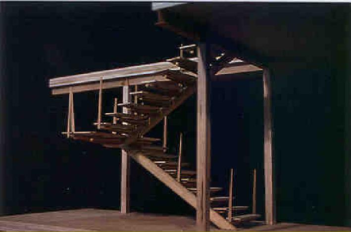
Far Right: a basswood model tests the theory of the structure and proves the spatial and conceptual ideas.
Right: the stair structure with railings in place prior to final paint and installation of the solid maple stair treads and landing.
|
|
|
|
|
|
|
|
|
|
|
|
|
|
|
|
|
|
|
 |
|
|
|
|
|
|
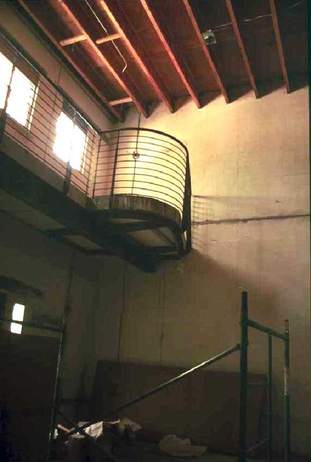
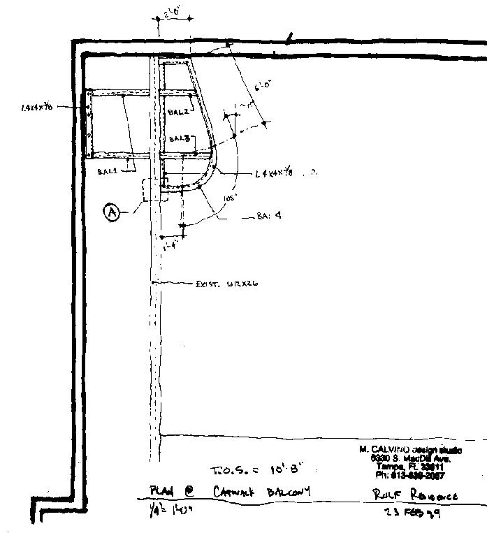
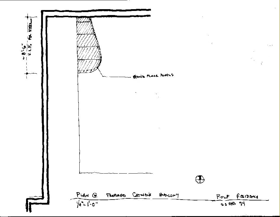
The other part of the project involved providing a seating area or hang-out spot at the end of a catwalk at the west end of the space. The structure is a pair of cantilevered angles springing from an "existing" W12x26 (already in the project). The cantilever is made under the autoclaved, aerated concrete planks and supports additional area enough to place a couple of chairs and a small table.
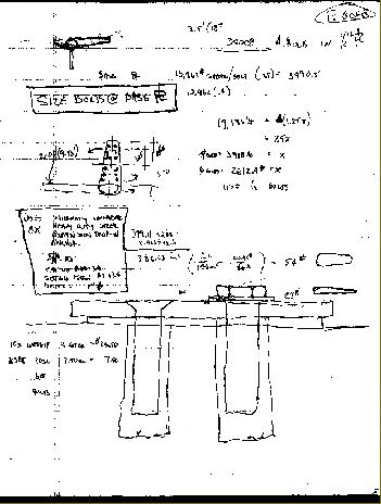
Structural calculations are employed to size and locate the steel members, the steel pieces are shop fabricated & then installed in the field.
Far Right: plan drawing of steel sub-structure.
Right: the completed stucture prior to finishes.
|
|
|
|
|
|
|
|
|
|
 |
|
|
|
|
|
|
|
|
|
|
|
|
|
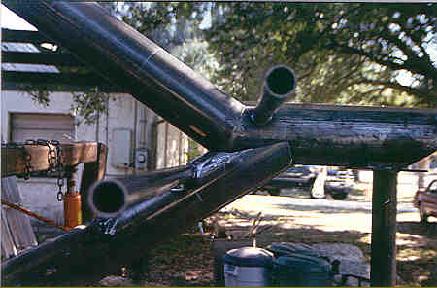
Below: a series of drawings and photos showing the development of the complex spine joint made with the 6" sch.80 pipe. (Autocad)
|
|
|
|
|
|
|
|
|
 |
|
|
|
 |
|
|
|
|
 |
|
 |
|
|
|
 |
|
|
|
|
|
|
|
|
|
|
|
|
|
|
|
|
 |
|
|
|
|
|
|
Right: the main explanatory drawing for the stair showing the overall configuration and connections, sections, sizes, and materials. (ink on trace)
|
|
|
|
|
|
|
|
|
|
|
|
|
|
 |
|
|
|
|
|
|
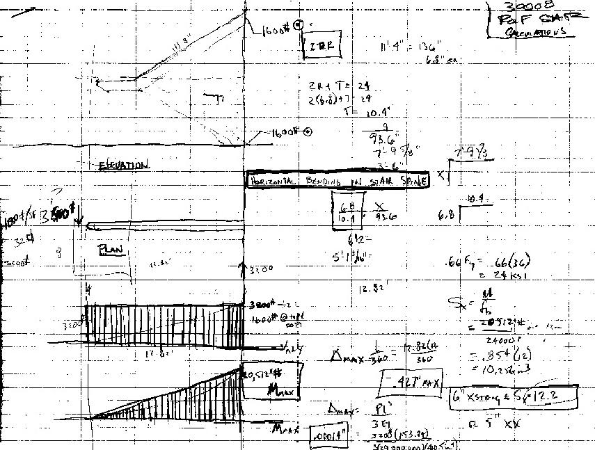
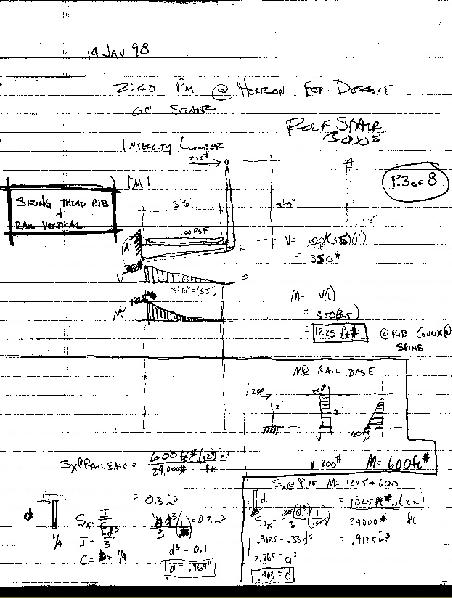
Far Right: partial calculations for the stair spine. Shear, moment, deflection, bending stress.
Right: Stair in fabrication location at Calvino Architecture Studio. Note the steel brace installed on the roof of the shop.
Below" Calculations for the steel base plate connecting the stair spine to the floor slab.
|
|
|
|
|
|
|
 |
|
|
|
|
|
|
 |
|
|
|
|
|
|
|
|
|
|
 |
|
|
|
|
|
|
|
 |
|
|
|
|
 |
|
|
|
|
|
|
|
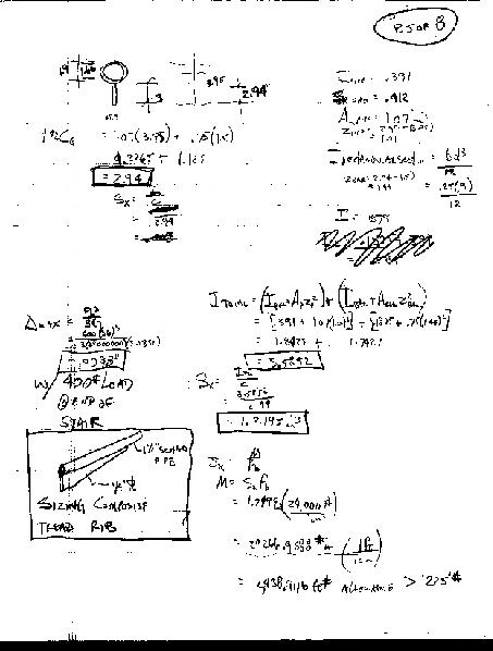
Far Right: Calculations for the stair tread support arms. The arms end up being a composite of a pipe plus a moment shaped steel plate )far right, lower) in order to keep the steel section small.
|
|
|
|
|
|
|
|
|
|
|
|
|
|
|
 |
|
|
|
|
|
|
|
|
|
|
|
|
|
|
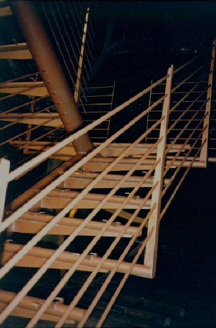
Above: The stair frame completed at the Studio
Right Middle: stair section specifying materials and welds for the tread support arms.
Right: detail of the fabricated tread support arms.
|
|
|
|
|
|
|
|
|
|
|
|
|
|
|
|
|
|
|
|
 |
|
|
|
|
|
|
 |
|
|
|
|
|
|
|
|
|
|
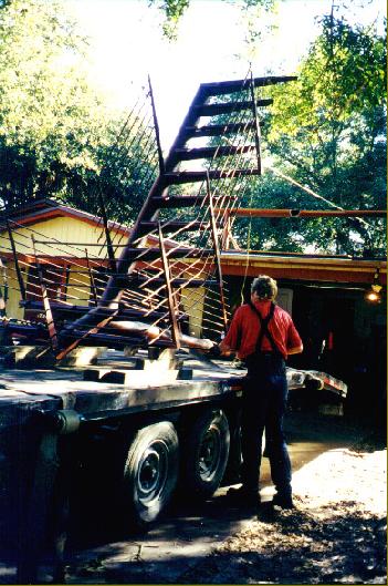
Right: Stair tread support pipes tack welded into place.
Below: Brilliant Ken Fleming helping (well, more like imparting valuable knowledge to) me loading it onto the transport trailer.
|
|
|
|
|
|
|
|
|
|
|
 |
|
|
|
|
|
 |
|
|
|
|
|
|
|
|
|
|
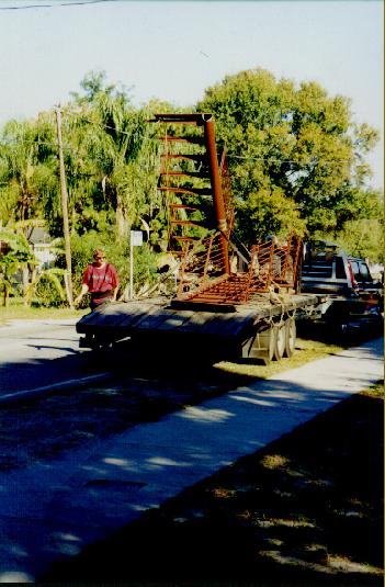
Above: The stair was simply cut free from the upper support, unbolted from the floor slab, then lowered using the shop crane onto the trailer once it was backed under the stair spine.
Below: Loaded up & strapped down, ready for transport. The transport load could not be more than 13' above the road surface because the lowest traffic light or overhead obstruction on a roadway is at 13'-6". This is where the CAD model and exact drawings of the transport trailer or whatever it is that you're dealing with comes in very handy.
|
|
|
|
|
|
|
|
|
|
|
|
 |
|
|
|
 |
|
|
|
 |
|
|
|
|
|
|
|
|
|
|
|
Far right: Plan at balcony showing the Aerated Autoclaved Concrete (AAC) panels.
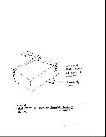
Right: Detail of the edge reinforcement for the balcony panels.
|
|
|
|
|
|
|
|
|
|
|
|
|
|
|
|
|
|
|
 |
|
|
|
|
|
|
Right: elevation of north wall existing
|
|
|
|
|
|
|
|
|
|
|
|
|
|
|
|
|
Right: elevation of north wall concept for wall sculpture/entertainment system/lighting.
|
|
|
|
|
|
 |
|
|
|
|
|
|
|
|
 |
|
|
|
|
|
|
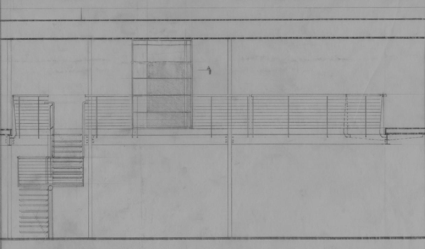
Right: elevation of south wall behind railing. Steel & glass door concept into master suite.
|
|
|
|
|
|
|
|
|
|
 |
|
|
|
|
|
|
|
|
|
|
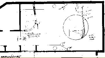
Above: Conceptual plan at master suite.
|
|
|
|
|
|
|
|
|
|
|
|
|
|
|
|
|
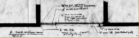
Right: plan at steel/glass door.
|
|
|
|
|
|
 |
|
|
|
|
|
|
|
|