|
Concrete Stair |

|
©2026 CALVINO architecture studio, inc all contents of this publication whether in digital or analog format are the express property of CALVINOarchitecture studio, inc. and shall not be reproduced by any means without written consent from Mike Calvino |
|
2004—designed nights on a makeshift drafting table—mostly with pencil & ink on trace . . . while staying in the Ruskin House Guest House while building the Main House there . . .
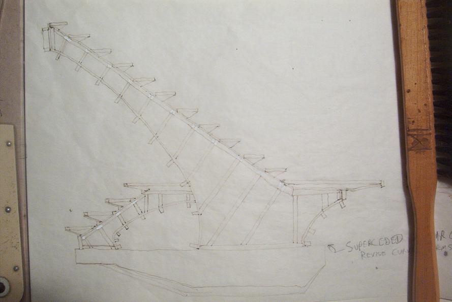
The idea was to make a sculptural piece as an entry that would draw one’s eye upward to the main entry door for this house at the water’s edge on a small island at the north edge of Ruskin, FL. The first thing that was apparent is that it had to be concrete—the most durable, the most resistant to the harsh salt environment that it’s in . . . The mangrove edge of Tampa Bay. This was great because it needed to be sculptural and what better material system to use than something plastic that has to be molded & formed.
Another requirement was that I decided that it could not be connected to the structure at the top landing. There were a number of reasons for this: first because the structure at that level is steel framing (structural steel) with light gauge steel studs then an outer finish of stucco. This would asking for trouble if one were to penetrate this assembly with anything to attach a stair. So, I knew it had to cantilever out of the ground! And what better way to give it some reason for being sculptural, right? |
|
The design of the project unfolded by the light of an old drafting lamp set up on a makeshift drafting table with a flat-panel tv from the owner playing Batman Begins & Spiderman . . . The idea was to have Robert Berg & his team of craftsmen build the forms & form the rebar & then he would have his concrete guy Kaminsky & Gary Ogilby there to finish it. So I set out to design the structure and the forms.
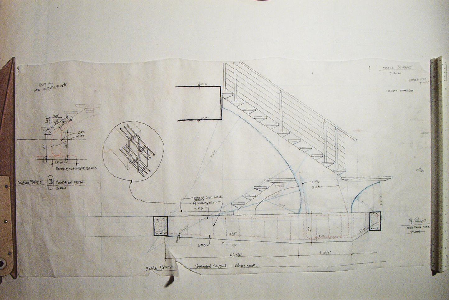
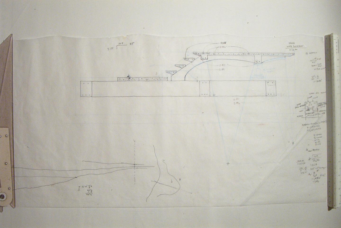
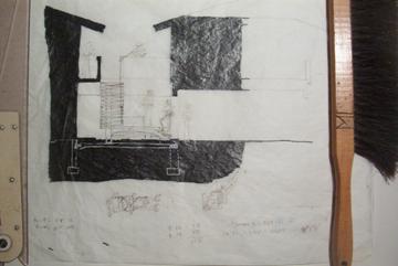
The main structure had to withstand waves crashing into it, so I designed a set of grade beams to anchor it to the existing concrete grade beams which were attached to creosote laden round wood pilings. The grade beams then supported a tapering cantilevered concrete mass that was sized to withstand the crashing waver forces & support the live loads of the stair & landing.
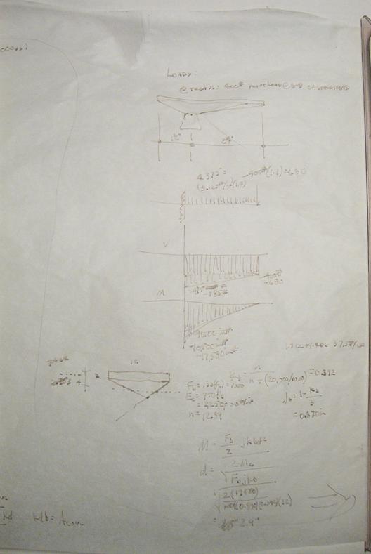
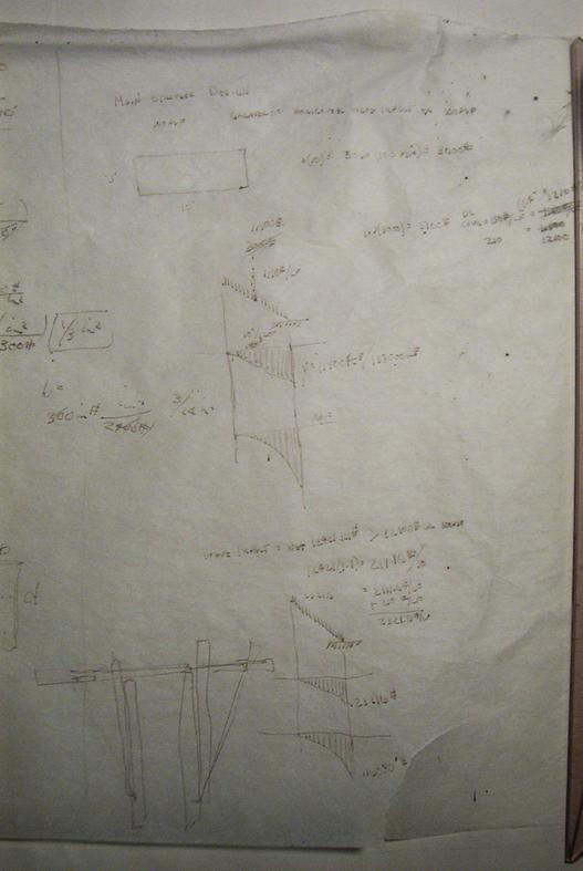
The concrete design was fairly straight forward using what we learned in Structures classes and fine tuning the process using ACI318. The taper is found by running shear & moment diagrams for the cantilevered beam (and the tapered grade beam) & then taking moments at intervals along it length to solve for depth and required area of steel. |
|
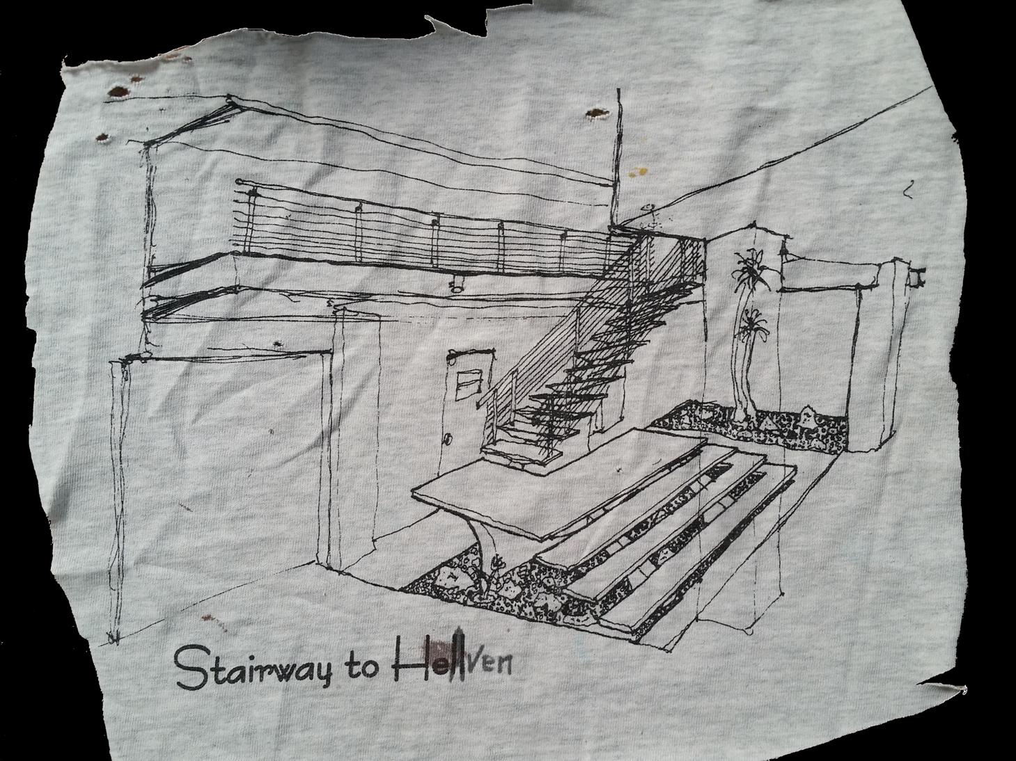
Right: the only version left of the first sketch was on a t-shirt that Rob Berg made for his guys while they were building the stair! |
|
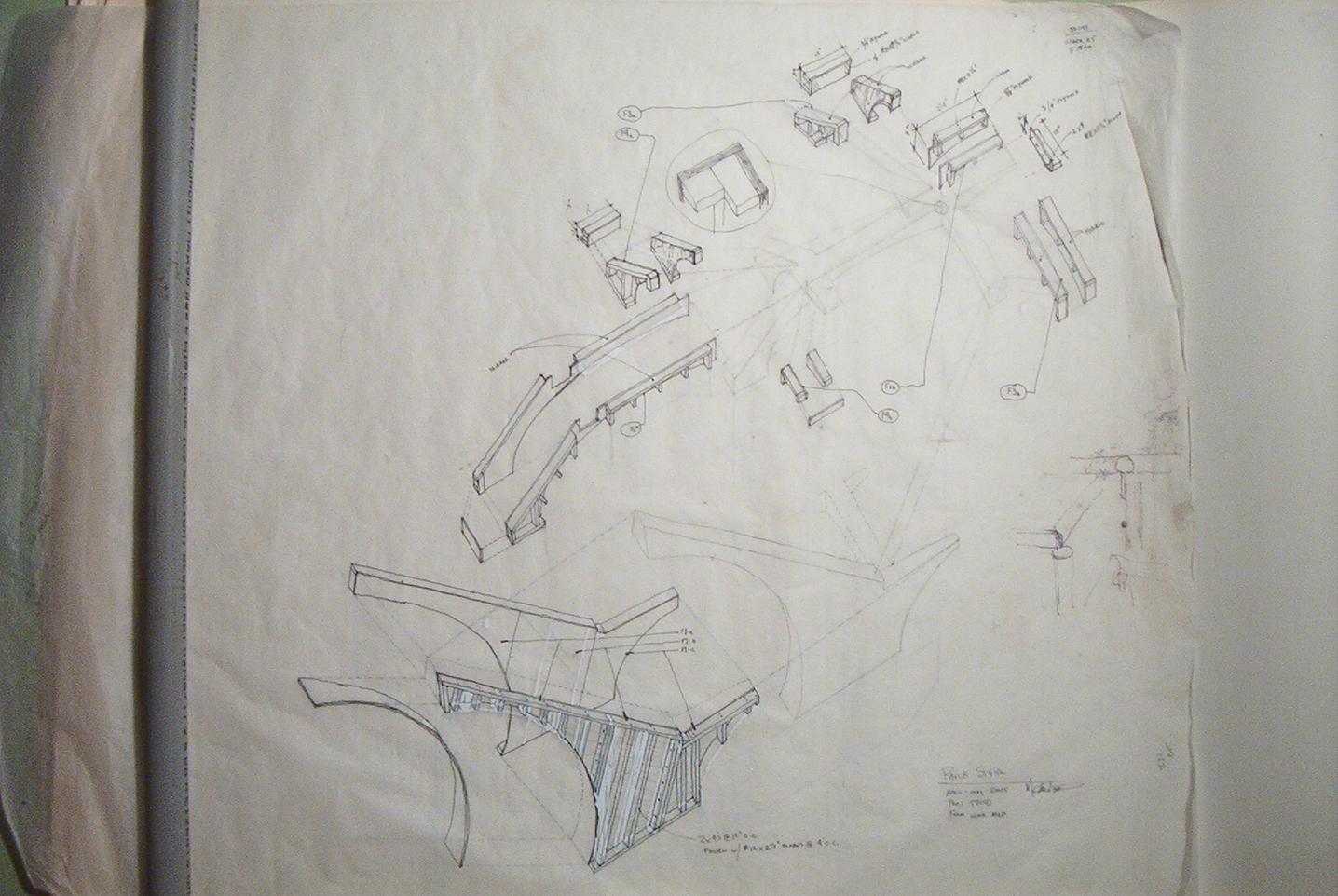
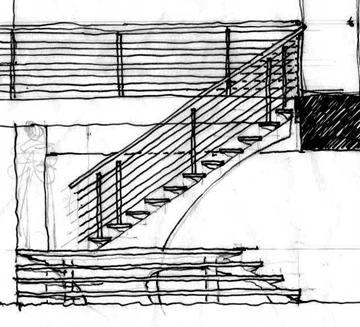
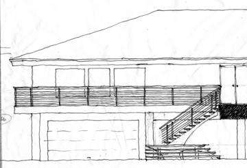
Above & below: pencil & ink on trace sketches proposing the stair. |
|
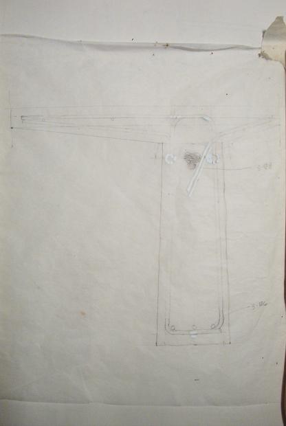
The landing structure is also just a series of simple span beams and cantilevered beams that are solved one at a time in the same way, calculating moment along the length of the beam, cutting a section there & solving for concrete depth & rebar area. |
|
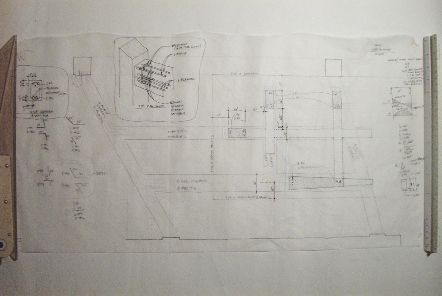
Here’s the plan layout showing how the grade beams connect to the existing pile caps & how the stair structure then springs from those grade beams. Shear & moment diagram over there in the margin & rebar connection details over here in the upper left . . . |
|
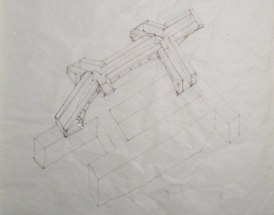
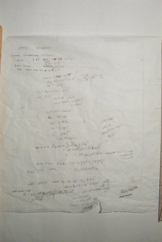
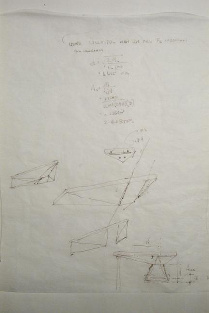
Here we go with some conceptual layout of how the forms will work & some more calcs determining the wave velocity and impact loading that it’ll have to withstand. |
|
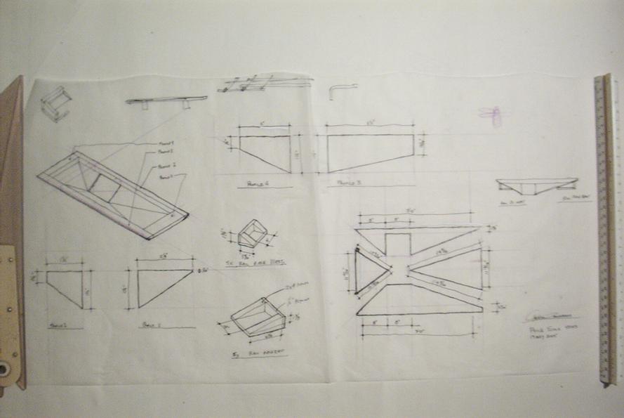
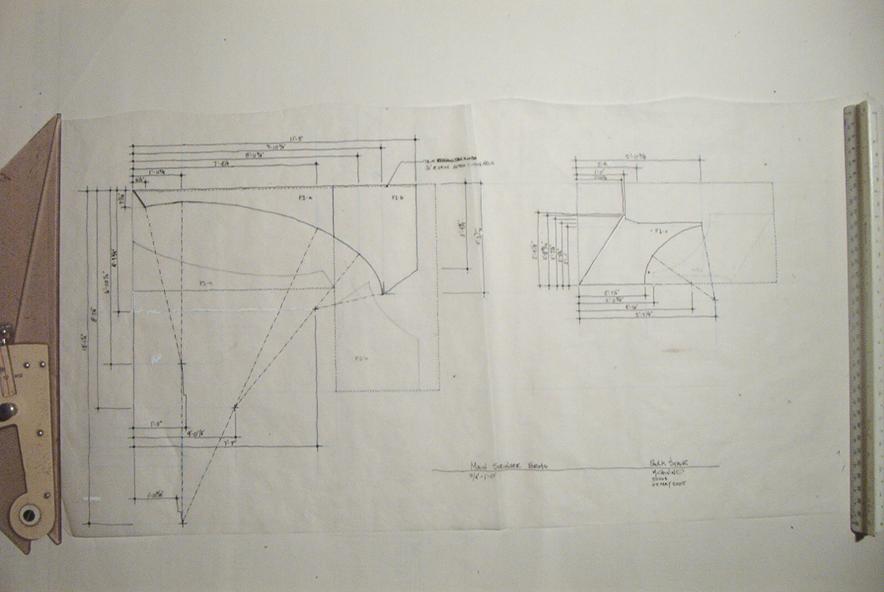
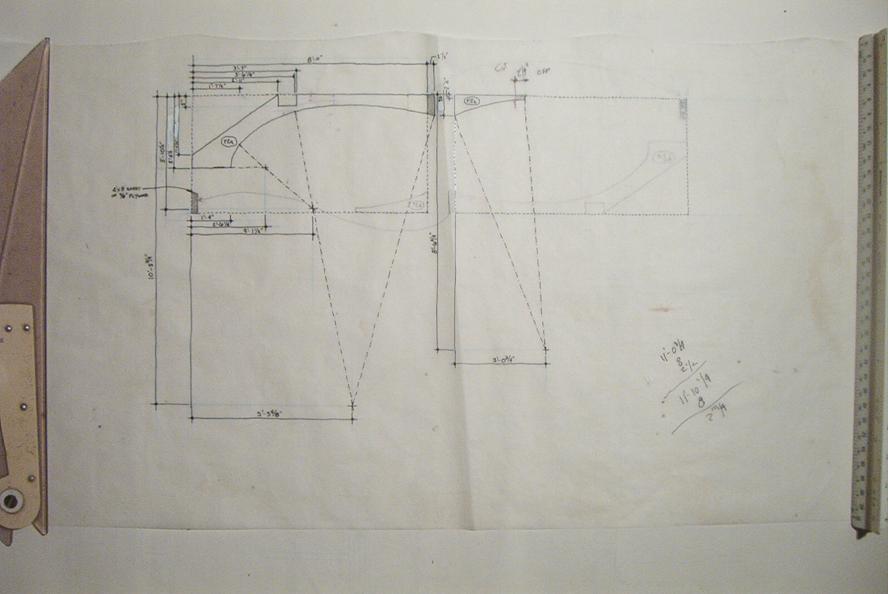
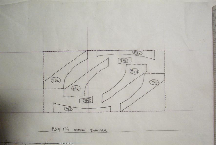
Here are some calcs for the forms and some layout drawings for how to cut the form boards for Robert. I ended up stopping over there and helping him lay out the radii for the main forms to get him started . . . He ended up saying, wow I though it might be that simple—to use a board, some string, and a pencil to lay out the shapes on the plywood to cut them out . . . |
|
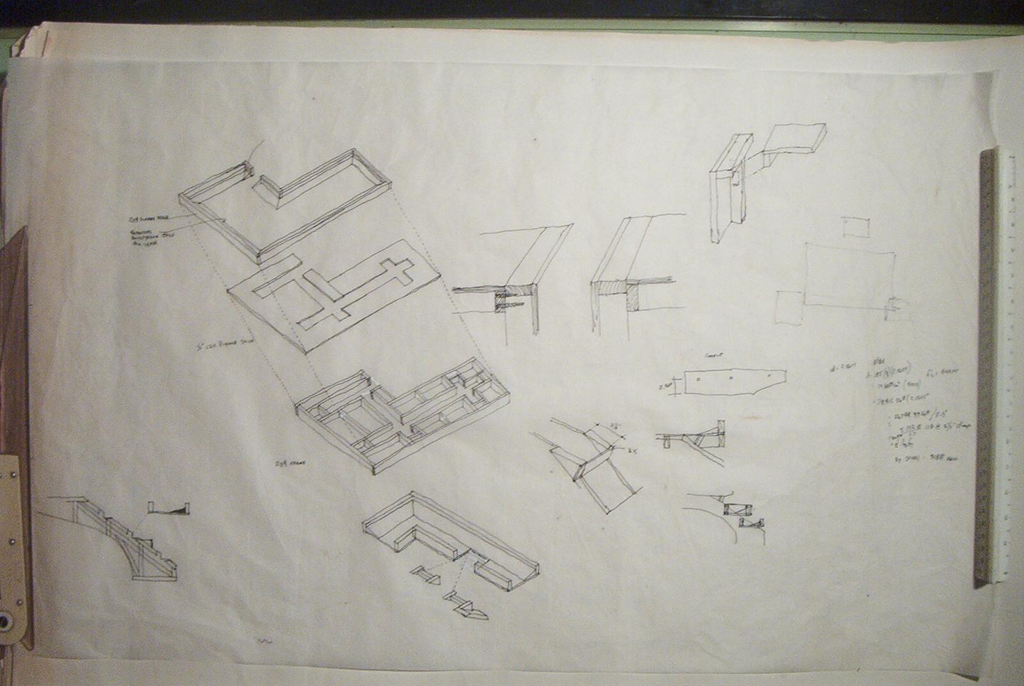
More drawings attempting to explain how the formwork is to go together . . . You can see on the ConstructionFab page that Robert & his crew did a great job with it . . . |