
|
Finished Photos | Construction | |
||
|
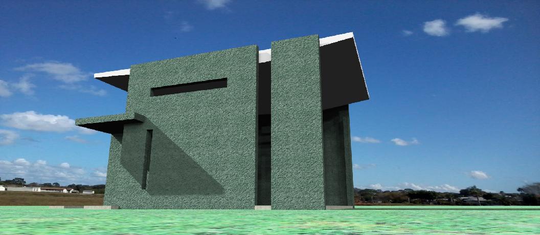
The challenge: create a space with minimal height that can accommodate a loft space with adequate head-room below and in the loft. |
||
|
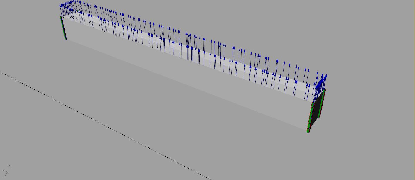
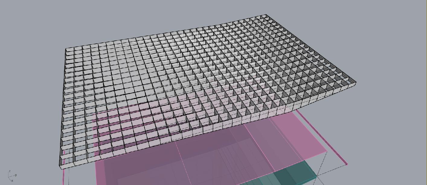
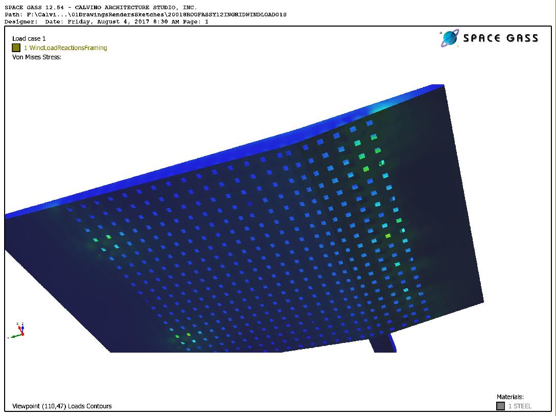
Right: the 20ga. Steel waffle core at 12" o.c. each way. This is the second version of the core as the first was at 16" o.c. and resulted in excessive deflection in the composite analysis. This 12" centers waffle on first round of analysis is resulting in approximately 0.604" deflection. More analysis is required to verify results at this point, but is seems as if the system will work. |
||
|
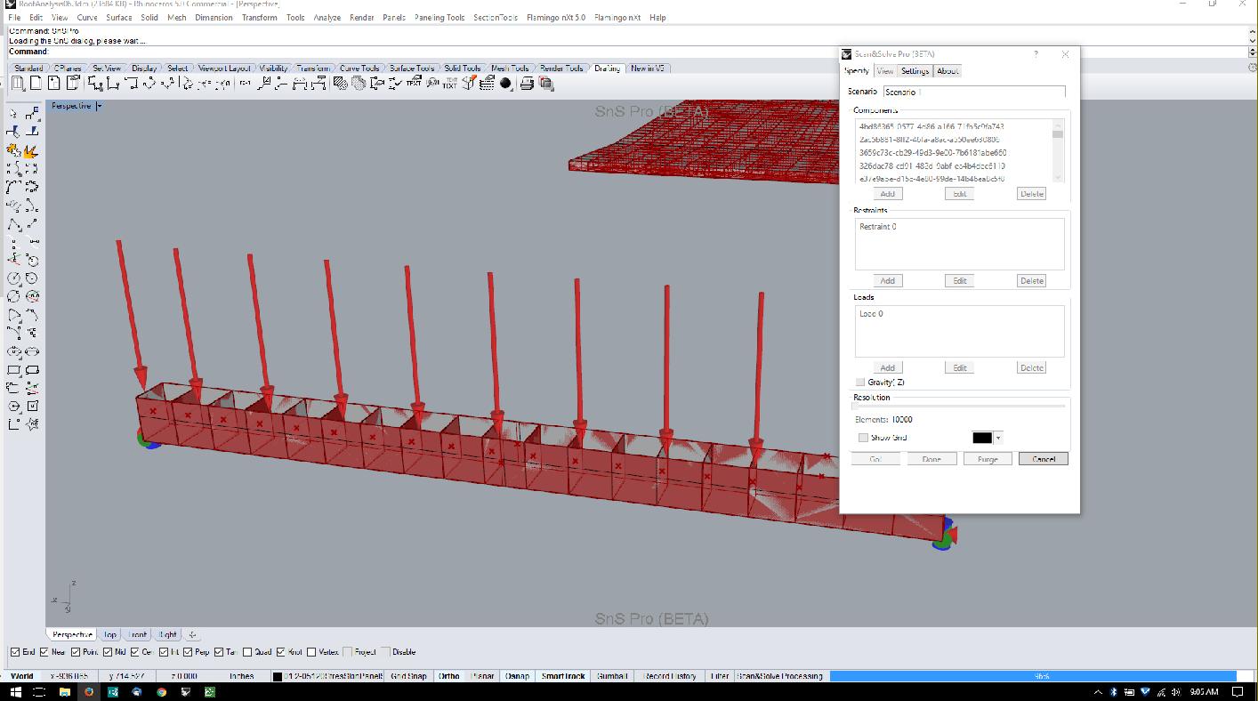
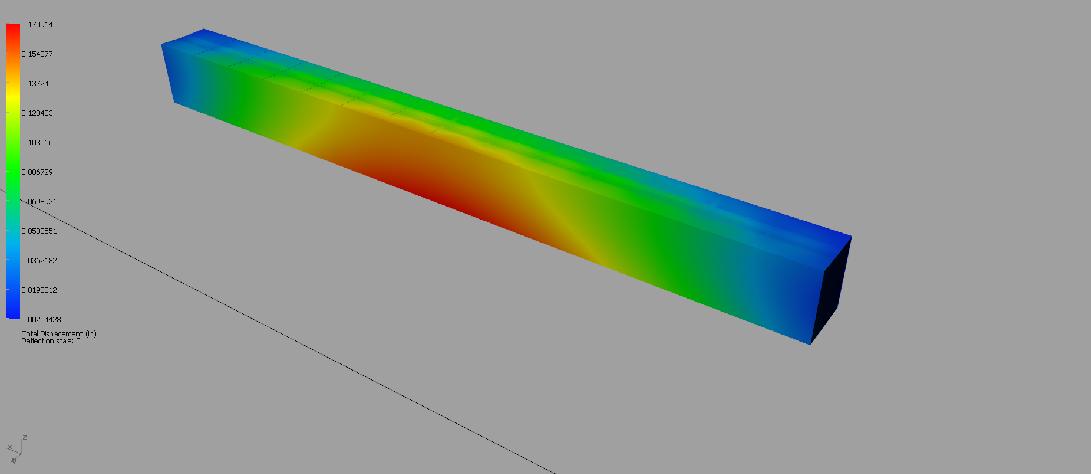
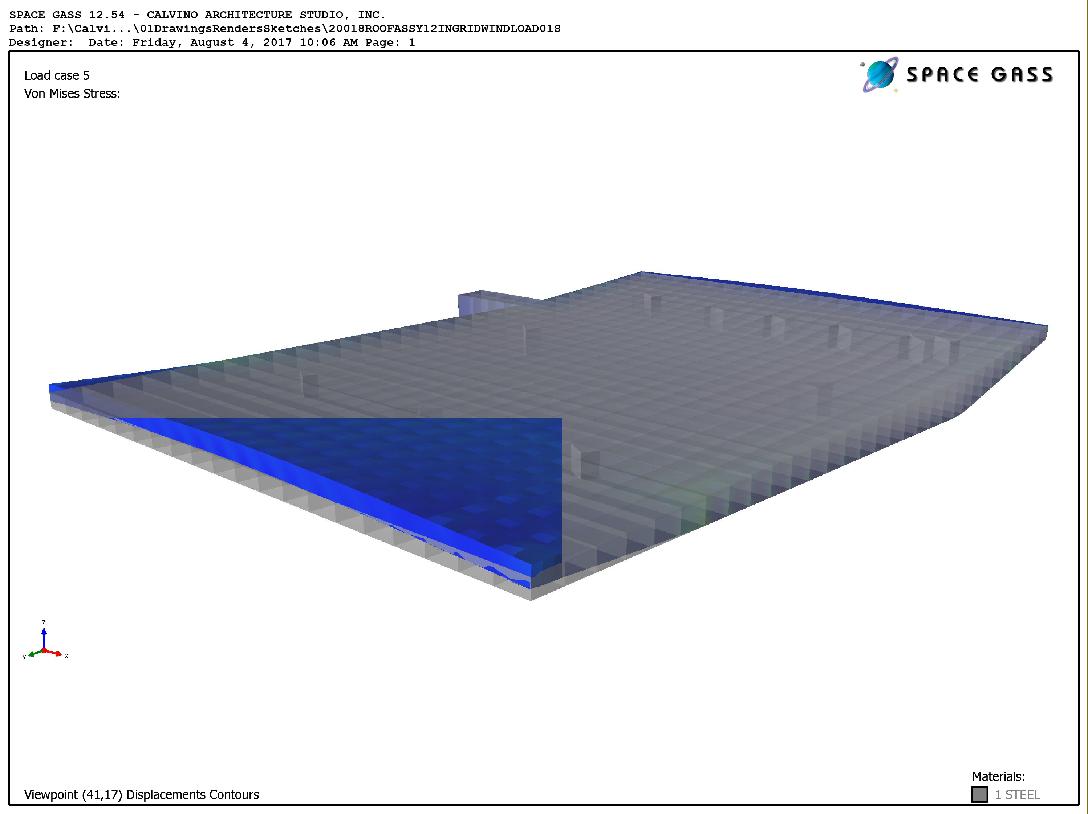
Right: Step 1 of the analysis is to run a simulation on a piece of the core in which the top edges are uniformly loaded, the beam is a simple span, and the top edges of the steel sheets are restrained in the X direction as they are laterally restrained by the stressed skin. This will allow only Y & Z deflections to be calculated and produce a situation where one can solve for the composite Elastic Modulus (E) using the deflection value computed by the Finite Element Analysis. This E can then be used as input for a material physical property for the center core grid along with the resultant density for the 12"o.c. grid. |
||
|
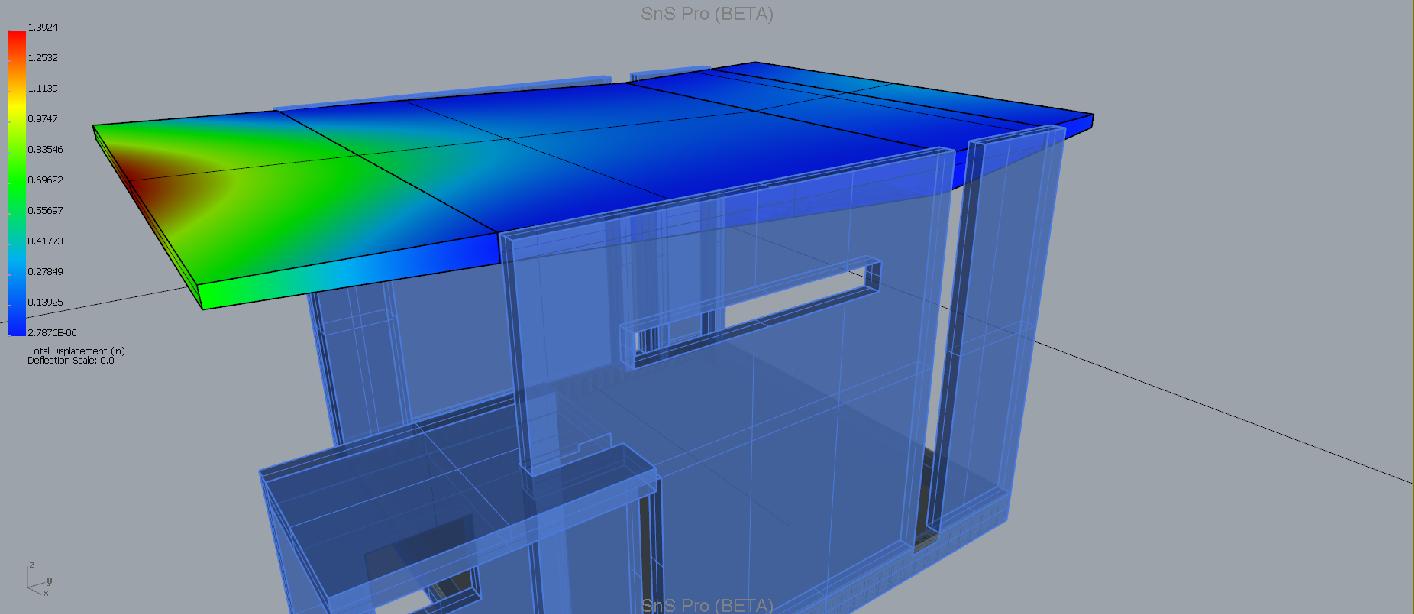
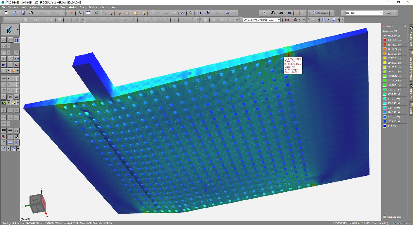
The second trial of analyisis is done using a program that can do thin plate analysis. The entire system is modeled and the loads and restraints are specified within the model. The stresses are shown both numerically and with a color-graded spectrum. Max streses are concentrated at the "spring" of the cantilever to the south as expected. Using 20ga. In these locations produced stresses a little too close to the stress limits so an area about 2'x4' will be fabricated using 16ga galvanized steel on the lower as well as the upper skin of the system. This lowers the stresses to the range near 50% of the allowable. |
||
|
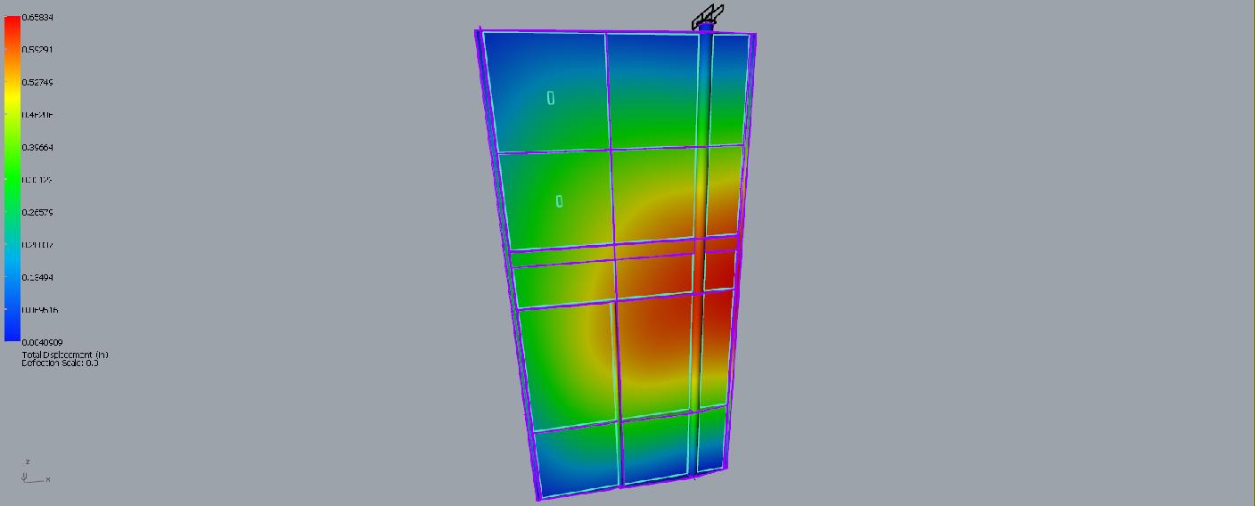
Main Door FEA displacement map |
||
|
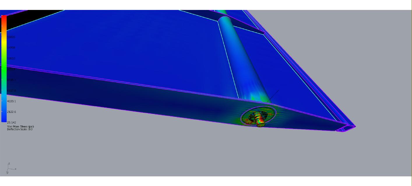
Main Door lower bearing FEA Stress map |
||
|
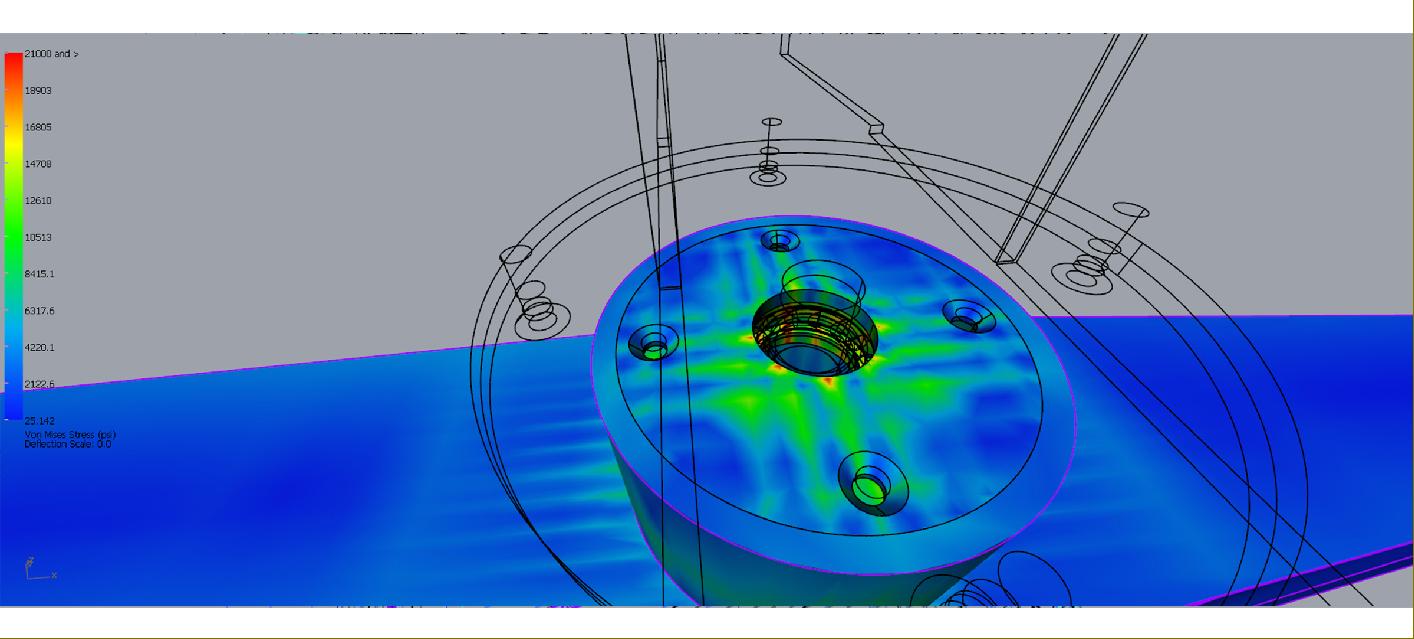
Main Door Upper bearing FEA Stress map |
||
|
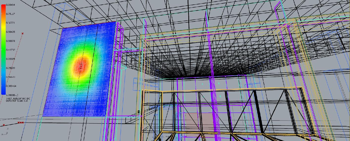
Worst case Glass lite impact FEA Deflection map. |
||
|
Finished Photos | Construction | |
||
|
|
||