Build Log 03 Y & Z Carriages --  5 axis CNC for Santiago Perez's FabLab

Back to Automation/CNCMachines

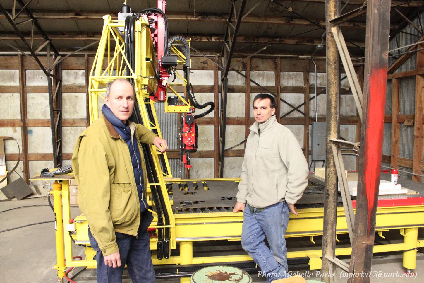
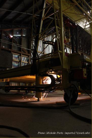
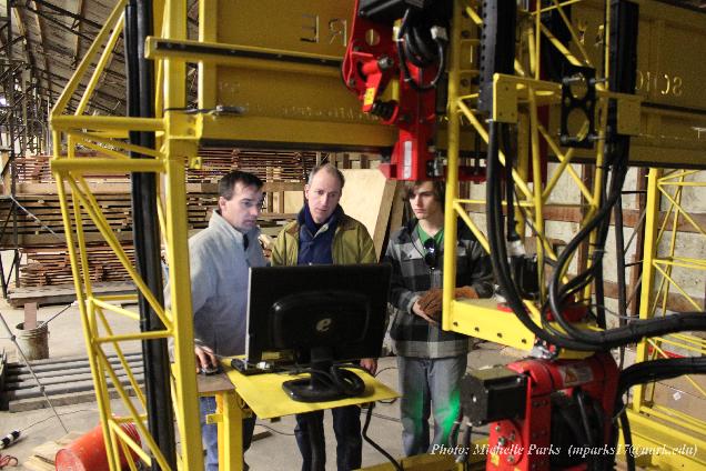
Build Log 03 Y & Z Carriages 2010

Some of Santiago's work with students can be seen here:
https://www.srplab.net/

https://www.youtube.com/@plab48

https://www.flickr.com/people/srplab/

   
https://www.flickr.com/photos/srplab/albums/72157626070158605

5 Axis Cnc for SrpLab's FabLab
Build Log 00--Design Log
Build Log 01 getting started and the table base
Build Log 02 gantry
Build Log 03 Y & Z carriages
Build Log 04 Motor brackets & gear systems
Build Log 05 manual motion
Build Log 06 A/C Head
Build Log 07 Spindle and A/C head motion
Build Log 08 Motors and wiring
Build Log 09 Electronics and control cabinet
Build Log 10 Self powered motion and testing
Build Log 11 Delivery and setup

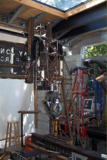
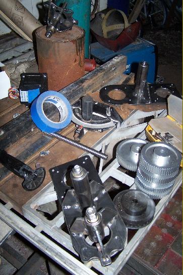
Right:  Y carriage highlighted

Right Lower:  Drilling the holes for bolting the Y bearing rails.

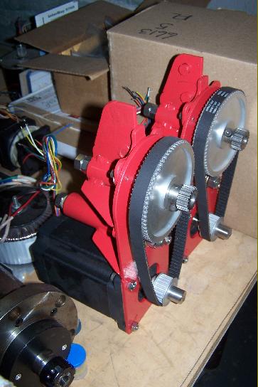
Above:  Aligning the motor bracket mounting tube on the Y carriage.

Right & Far Right:  Y carriage main frame after weld-up.

Below:  Rhino working model showing overall configuration.  This is the starting point and the place to go to figure out what to do when things don't go as planned . . .

Right:  The tapped holes for the bearing rails can be seen on the inside of the far tube of the Y carriage.  The light gauge steel tracks on the back side are guides for the cable carriers.

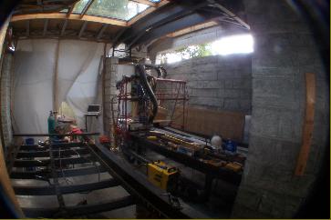
Right:  The Y carriage at first installation.

Far Right & Far Right Lower:  detail showing bearing blocks & linear bearing tracks for Y carriage.  The round mount plates are for the Z axis Ball Screw.

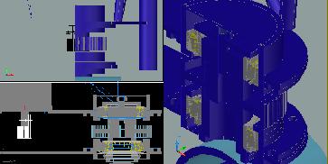
Right:  Rhino working model showing the Z carriage.

Right:  Z carriage in wire frame mode showing part of the belt/pulley reduction assembly inside the C axis mounting box.

Below:  Original AutoCad Model of the Y/Z Carriage

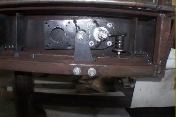
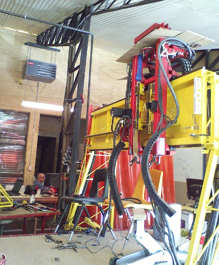
Right:  The assembly after the Z carriage main frame is assembled & mounted on the linear bearing rails.  Just prior to fabrication of the C axis mounting box.

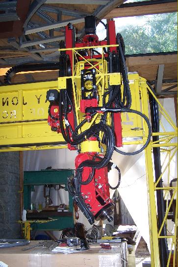
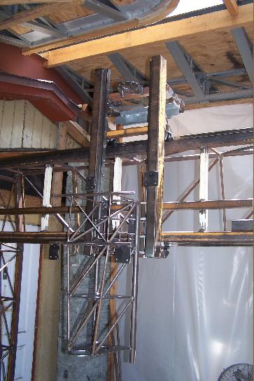
Right & Far Right:  the Z Carriage

Right:  detail of Z carriage stiffening truss structure.  The trussed structure helps to keep the weight down and stiffness up so that the machine can be run using lower powered & motors, controllers, & power supplies to keep costs in the affordable range.

Right:  AutoCad Wire frame view of model prior to "flipping" the gantry side verticals.  Note the eccentricity of the loading on the gantry bearings.

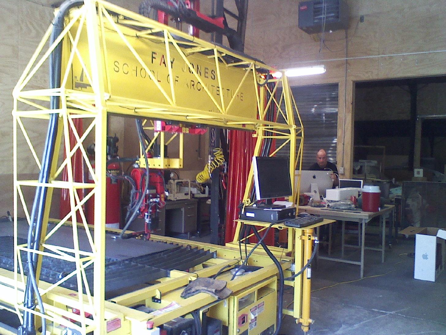
Right:  Rhino working model with the gantry, "flipped".  Z carriage assembly with A/C axis assembly on.

5 Axis Cnc for SrpLab's FabLab
Build Log 00--Design Log
Build Log 01 getting started and the table base
Build Log 02 gantry
Build Log 03 Y & Z carriages
Build Log 04 Motor brackets & gear systems
Build Log 05 manual motion
Build Log 06 A/C Head
Build Log 07 Spindle and A/C head motion
Build Log 08 Motors and wiring
Build Log 09 Electronics and control cabinet
Build Log 10 Self powered motion and testing
Build Log 11 Delivery and setup

©2023 CALVINO architecture studio, inc  all contents of this publication whether in digital or analog format are the express property of CALVINOarchitecture studio, inc. and shall not be reproduced by any means without written consent from Mike Calvino