
|
|
||
|
Back to Automation/CNCMachines |
||
|
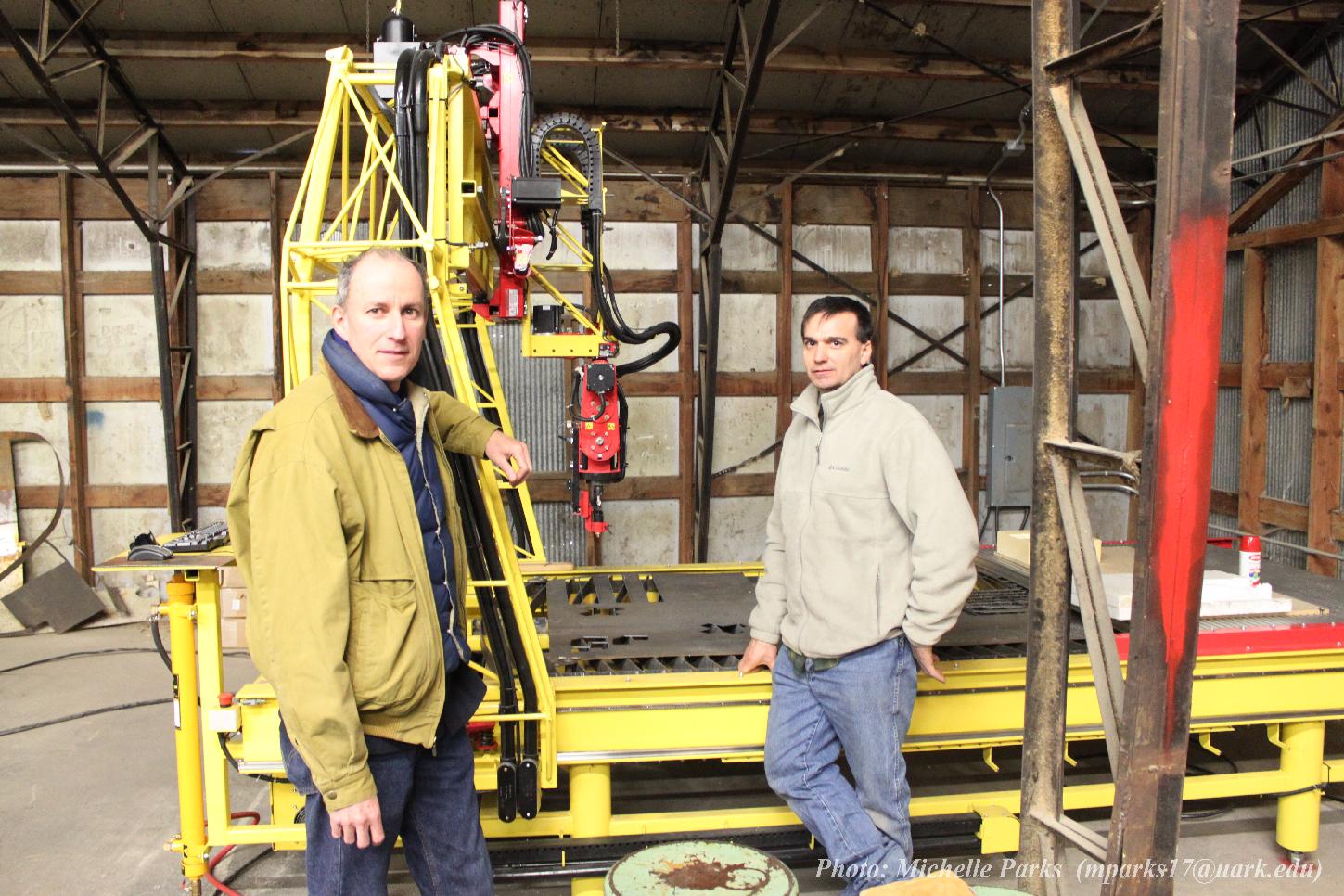
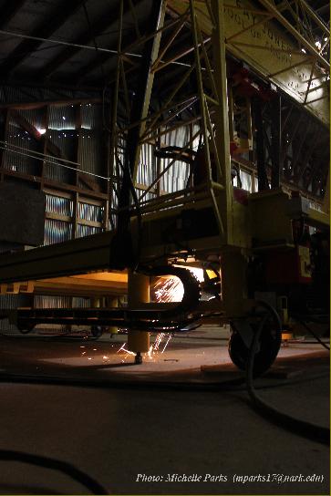
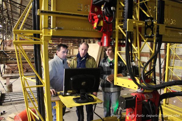
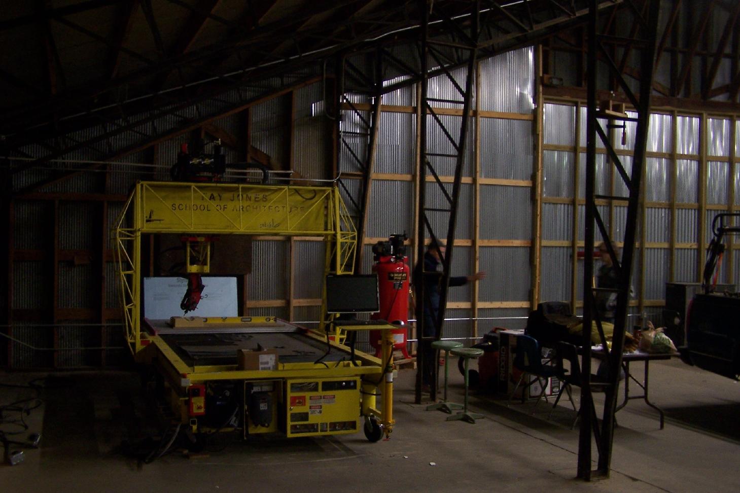
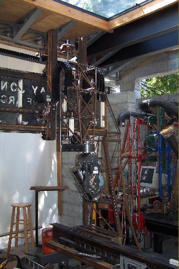
Build Log 08 Motors and wiring 2010 |
||
|
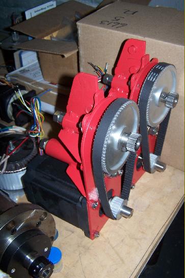
The given parameters--motors, drivers, switches . . . |
||
|
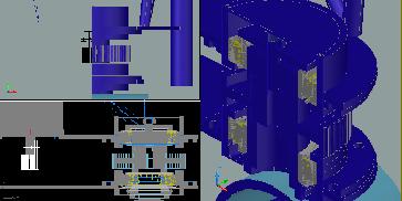
More known variables: wiring diagrams and equipment dimensions. |
||

|
Sketches beginning to quantify and give form to the requirements. |
||
|
Right: motor wiring lengths and conduit sizes, lengths & components, communication wiring lengths & locations. |
||
|
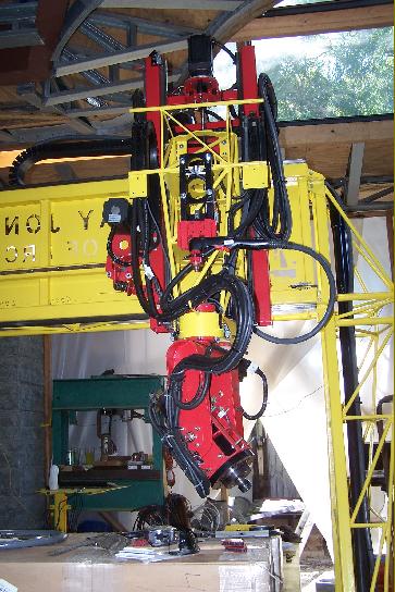
Right: Spindle power and control wiring |
||
|
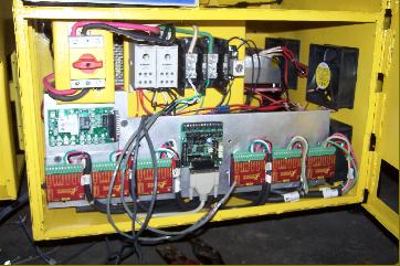
Right: motor and component power circuit layout concepts & cabinet organization with wattage to balance system. |
||
|
|
||