
|
|
||
|
Back to Automation/CNCMachines |
||
|
Build Log 06 A/C Head 2010 |
||
|
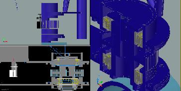
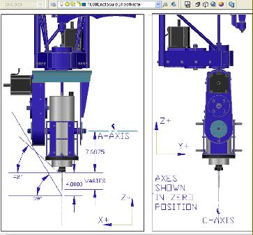
Below: Sketches of the C gear housing |
||

|
Below: sketches of the gear redection pulley & belt system |
||
|
Above: sketches & misc calcs of the gear reduction system and ideas for the X axis hard stops. |
||
|
Above: gear reduction pulley machining numbers for the lathe. |
||
|
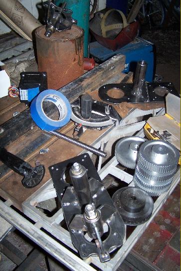
Right: the C shaft with the milled flats for the set screws of the pulley. |
||
|
Right: Milling the C shaft flats for the reduction pulley set screws using the 3 axis & generating G-code in the YZ axis instead of XY. |
||
|
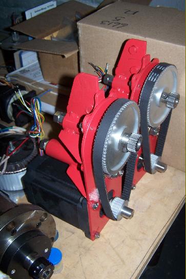
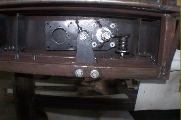
Right: the A axis belt reduction housing face plate & the reduction pulleys--they are milled separately & press fit on the shop press. |
||
|
Below: Machining the A & C reduction pulleys from a stock rod. |
||


|
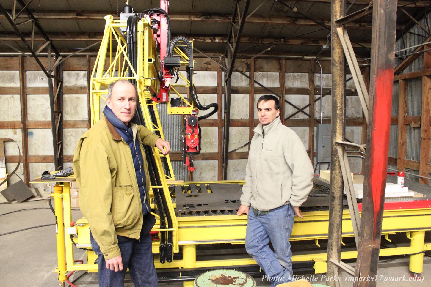
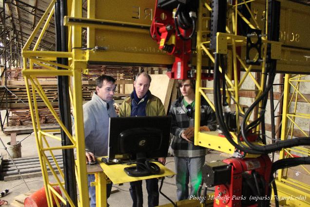
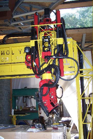
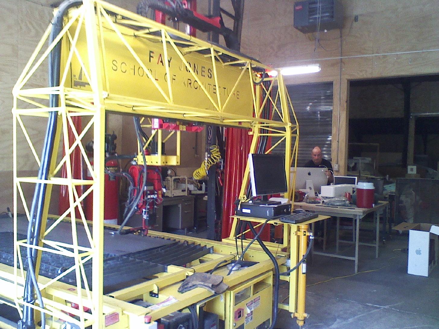
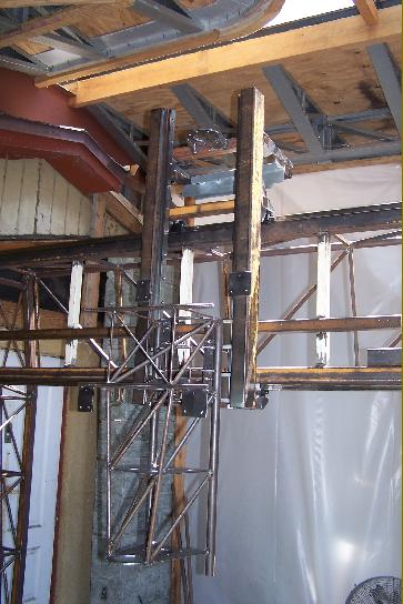
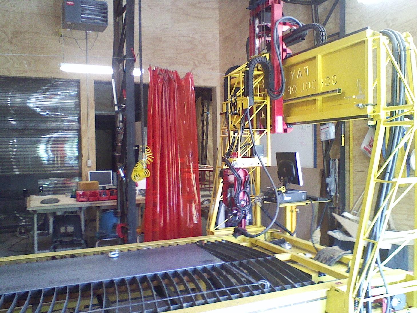
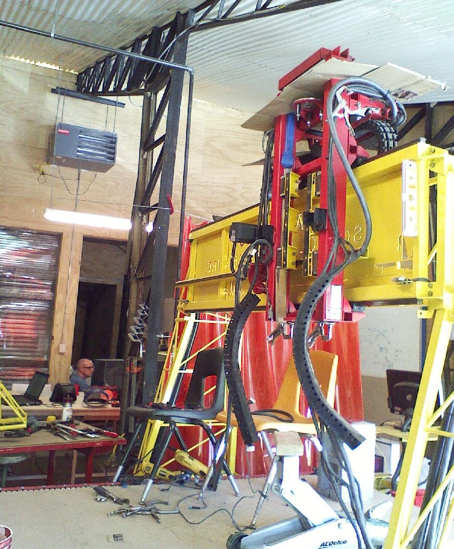
Right: A little motion test here of the a/c axes . . . |
||


|
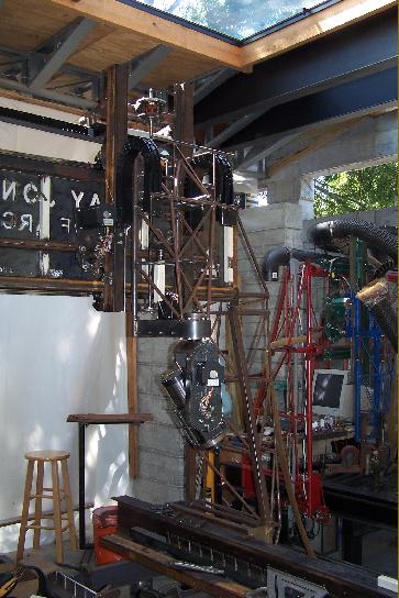
Right: Gear reduction systems completed for the A & C axes. |
||

|
|
||