
|
|
||
|
Back to Automation/CNCMachines |
||
|
Build Log 04 Motor brackets & gear systems 2010 |
||
|
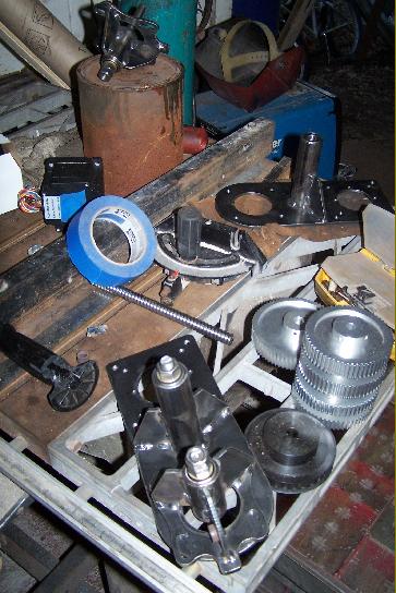
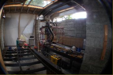
Right: The parts, plans & supplies for the project |
||

|
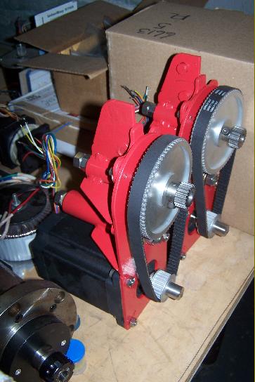
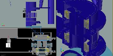
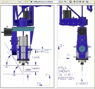
Right: AutoCad Model of the belt/pulley gear reduction, spring loaded, motor bracket. |
||
|
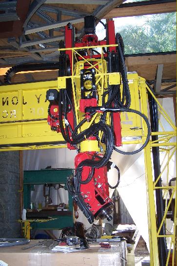
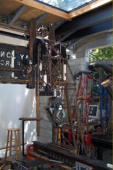
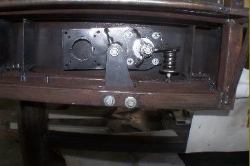
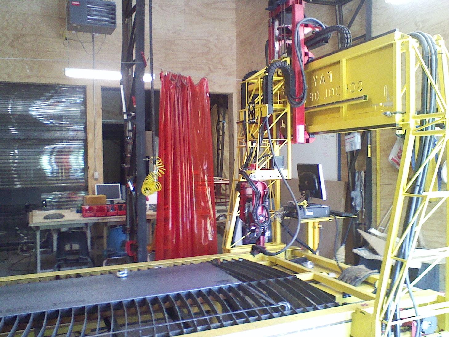
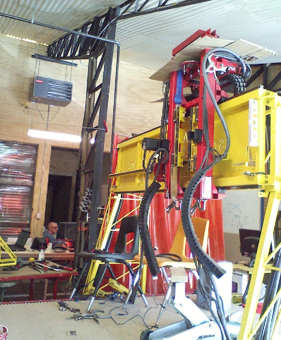
Right: X motor bracket in place with motor bolted up & Small Block Chevy double valve spring in place keeping the Pinion firmly in the Gear Rack. |
||
|
Right: Turning a Motor Bracket main mounting shaft housing. |
||
|
Far Right: Assembled X motor bracket |
||
|
Above: Broaching the Keyway in the X axis pinion gears. |
||
|
Right: Gear reduction shaft for X & Y Pinion Gear. |
||
|
Right: AutoCad Model showing the Y motor bracket. |
||
|
Right: Y motor bracket |
||
|
Far Right: Y Motor bracket rack & pinion--tight clearance between pinion face & rack mount tube. |
||

|
Above: Z axis ball screw nut at Z carriage attachment plate. |
||


|
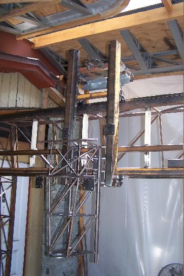
Far Right: Y/Z carriages assembled & mounted. |
||
|
|
||